
")

")


All heater cores are designed by Peter van den Berg, unless stated otherwise.
1: Brick core
A masonry firebox and riser is the simplest to produce, although fire bricks need to be cut. By using an optimized design this cutting could be minimal.
(read more)
P-channel
This duct supplies the secondary air in the original design. Simply constructed, it works solely due to the law of physics known as the Bernoulli principle.
(read more)
2: Brick core
The problem of the non-round riser of the brick core above is solved in this second design, the riser is now octagonal which is a better approximation to round. The layers are applied alternately on edge and flat in a reasonable running bond.
(read more)
3: Cast core
This is a firebox assembly together with the lower third of the heat riser in two separate parts. This one is built already quite often and works well but is vulnerable to cracking.
(read more)
4: Cast core
This is a recent design (2015) with the firebox divided into three parts. Instead of a p-channel there's a floor channel present.
(read more)
Floor channel
Also a secondary air supply but this one applies the air halfway in the height of the port. This duct lies on the floor of the firebox and recieves its air from the main air inlet.
(read more)
5: Cast core (sidewinder)
A design where the riser isn't situated behind the firebox but at the side instead, allowing a shallower depth.
(read more)
6: Brick sidewinder
A simpler way to build a one-off sidewinder as compared to making molds and cast the parts is building from firebricks. Unfortunately the number of bricks to be cut is quite substantial.
(read more)
7: A simpler core design
A combination of a square riser and a floor channel. Simpler to build, less cutting of bricks and still very good results.
(read more)
8: Double Shoebox Rocket
Variants that require a considerably smaller installation height. Compact, with a character all of its own.
(read more)
1: Straight brick core
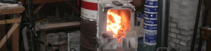
Using a good layout and a suitable clay/sand mix this masonry version is an easy way to test these principles for yourself. This can be done outdoors, in a barn or shed, anywhere that is convenient. A word of warning, the riser will likely have flames shooting out of the top, so use chimney pipe to vent when tested in enclosed spaces. It is not 'only' a convenient test bed, it is more than suitable for permanent use as the core for a space heater (the clay sand mix allows for easy disassembly after testing). As will be described later, space heaters take advantage of the ultra clean burn provided by these combustion units and are able to capture and store the heat produced.
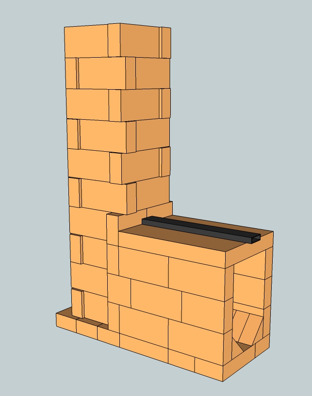
Of course it's sensible to build on stable footing, preferably insulating or using an intermediate insulation layer. The drawing in SketchUp 8 format of this design is available to download via this link. The internal shape of the riser is square, this is not as good as round, it will work but the shape isn't optimal. This version is suitable to build out of hard fire bricks. The layout of these bricks may need adjustment, this design is based on a brick size common in the Netherlands. Naturally, at least the riser should be surrounded by heat resistent insulation material. This isn't the case when this core is built using light weight insulating fire bricks. On the other hand, these are probably just a tad too vulnerable to abrasion to be used in the firebox.
P-channel
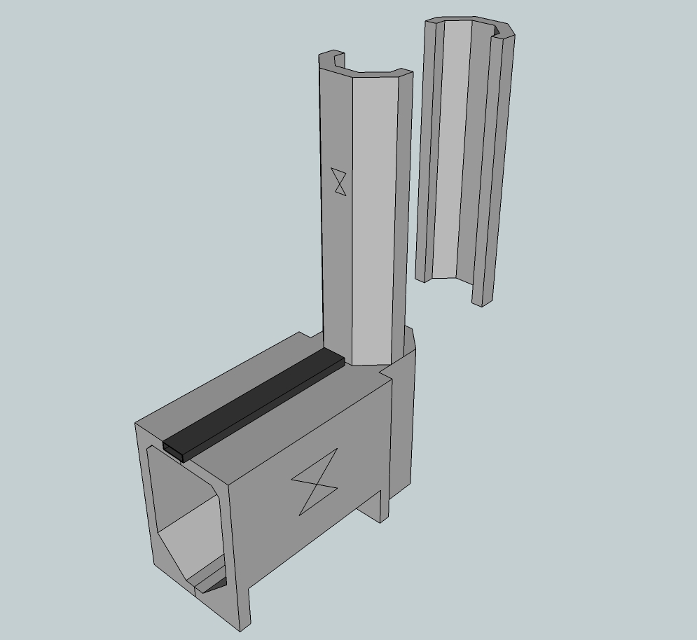
The steel rectangular duct on top of the firebox provides the secondary air supply. This part is commonly called the p-channel, short for Peter channel after its designer. Common mild steel or stainless steel is suitable material to manufacture this part. In this 150 mm (6") system a rectangular duct of 60x20x2 mm (2.36"x 0.8 " x 0.08") is being used.
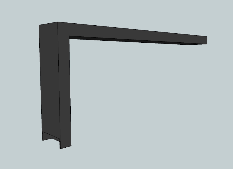
The downward hanging end stops a little lower than the top of the port, providing a small overhang. To keep things simple, this overhang is the same as the depth of the channel. At the back which is facing the riser a small piece is cut out to promote the suction of air. The same principle that causes the p-channel to work, Bernoulli's principle, means the pressure within the system is lower than that outside. Hence no smoke will escape the p-channel, indeed any other small cracks or the main air inlet itself. Conversely, if smoke does come out of the p-channel or main air inlet, then it means there is something wrong in the system.
This secondary air needs to be added to the stream in advance of the strong turbulence in the port and behind. Supplying air in the riser itself seems obvious but it won't work, mixing isn't powerful enough this way.
The duct is being cooled by the incoming air so the life expectancy of common steel is surprisingly long. Damage by corrosion in a space heater which has been used for two seasons is barely visible. So, it would be wise never to shut off the p-channel during operation. It is suspected a larger wall thickness of the duct could promote quicker corrosion because the steel can't shed heat as fast as the thinner material.
2: Straight brick core, octagon riser
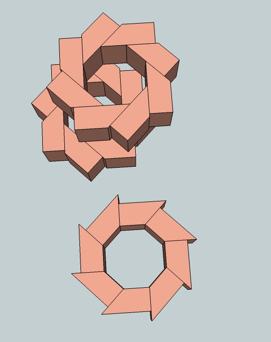
The problem of the non round riser is solved in this next design, the riser is octagonal now which is a better approximation to round. The layers are applied alternately on edge and flat in a reasonable running bond. The smoother the riser inside the better, so it's rewarding to be very careful when building this part.
The octagon is a favorable shape because this way the double vortex will initiate earlier in the burn. The drawback of this shape is the higher mass. Such a disadvantage won't be in play when insulating fire bricks are used for this build. Even insulating material around the riser isn't necessary anymore, the bricks are insulating enough by themselves.
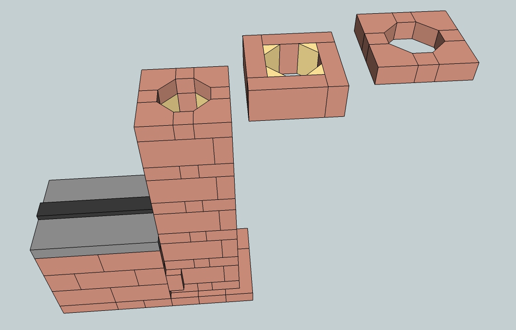
The small yellow triangles are in reality the same material, the different color is only there for easy visualisation. Construction of this core is different from the first brick design, the connection between firebox and riser is dissimilar. This drawing is available for download too, use this link.
Below are two other examples of how to make the riser octagonal out of normal brick sizes. Both use bricks that have been cut with a 45 degree angle to create equal sized "halves" to form an octagon shape. The lower one is simple but allows only one size of riser while the other allows the bricks to be adjusted to a slightly wider riser. A wider riser would mean the firebox and port should be wider as well, the scaling method still applies.
3: Straight cast core, 4 parts
This a tried and proven design with quite a few successful examples around the world. One conspicuous although not fatal flaw is the fact that this version is prone to cracks left and right in the firebox. The firebox will stay whole, after the cracks have appeared nothing much will happen later on. Probably the cracks themselves act as expansion joints, tension is released and the cracks won't grow anymore. Thickness of the walls are as thin as 30 mm (1.18") and where applicable fill pieces are used to economize on material. This isn't done to save money but to reduce the mass of the core. The less material in there, the sooner the thing is up to working temperature.
The part of the riser above the firebox is also split up in two parts which are identical so those could both be cast in the same mold.
The cross on the sides indicates which side is on top during casting. That side will remain relatively rough but that's of no consequence. Not only is the octagon a preferred shape (a very good approximation to round) it is also easily formed when building a mold. A table saw set to 45 degrees will cut all of the pieces required. Careful use of a hand held electric saw with a fence/guide will also serve if a table saw is not available.
This drawing is also free to use, downloadable via this link.
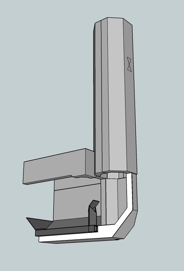
4: Straight cast core, 5 parts
This design is quite recent (2015) and has been in daily use for one winter without visible cracks. In my implementation the bottom rests on a support frame and the upper side is held together by cams and corresponding recesses in the top part. The picture below shows a slightly adapted drawing but is essentially the same as the one in my own heater.
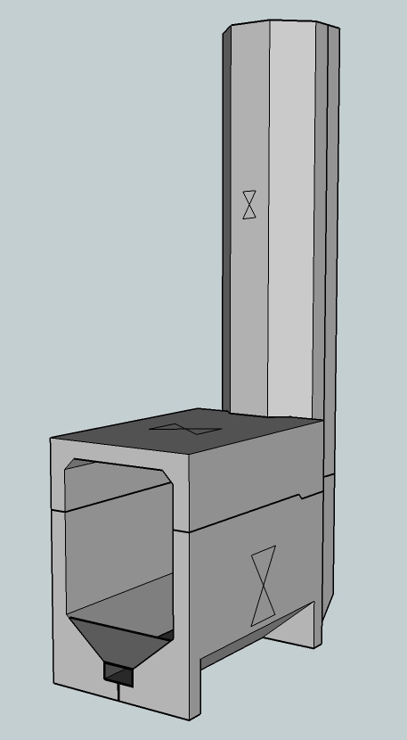
Naturally, the riser of this one need to be insulated from top to bottom as well. Construction is fairly simple, shown by the picture below.
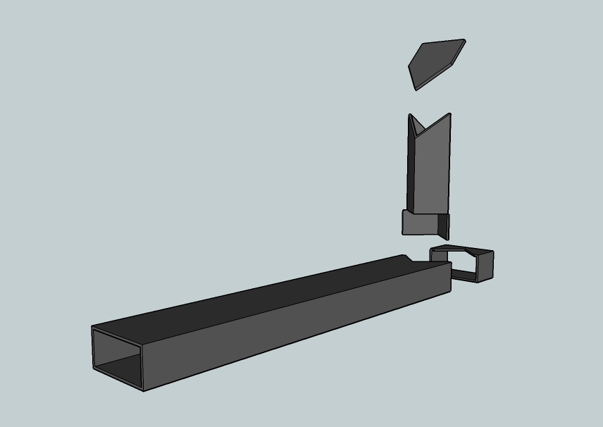
Floor channel
This secondary air supply duct is an alternative to the p-channel, not to be used in the same heater. The construction and placement is quite different, it lies at the floor of the firebox in a trench and it is fed through the same inlet as the main air supply. It is called a floor channel and as such it is a variant of Matt Walker's pre-port tube but the vertical part is shorter, square and less wide. As a consequence, the tube is less of an obstruction inside the firebox.
On top of that the air is supplied halfway up the port which in turn keeps the double vortex low in the riser on average. This version is somewhat easier to produce than Matt's, the only tools used to produce this thing is a small grinder equipped with a cutting wheel and a welder. This floor channel is very easy to replace, an advantage as compared to the p-channel which can't be taken out unless the heater is opened up.
The channel is made out of normal 2 mm thick steel rectangular duct and has very little corrosion or deterioration after a year of daily use in a temperate marine winter. The explanation for the lack of corrosion is that the inside of the duct is cooled by the incoming air. And the duct itself is in an oxygen poor corner of the firebox while the burn is going on, steel won't corrode in the absence of oxygen.
So, this is one of the few steel parts inside the firebox which isn't destroyed in ten runs, durability is reasonable. My next channel will be made out of stainless steel 304, life time expectancy should be even better.
The burns during winter of 2015/2016 were entirely dedicated to get this air supply right, about 12 variants have been tested. The drawing shows a horizontal duct of 60x30x2 mm (2.36" x 1.18" x 0.08") , the vertical piece measures 35x35x2 mm (1.38"x 1.38" x 0.08"). The internal cross section area of the larger duct is about 1.5 times as large as the smaller one. This is not a coincidence, three sizes of the horizontal pipe are tested in several combinations with three vertical sizes. The duct of 60x30x2 is just as effective as a 60x40x2 item, as long as the inlet is larger than the exhaust of the channel. Using the steel ducts as drawn, the vertical part is 5.4% of the riser CSA and the horizontal part 8.25%. By keeping close to these percentages it is possible to calculate the dimensions for a larger or smaller batchrocket according to their larger or smaller riser CSA.
01/05/2019 A somewhat simpler construction together with a larger feed part and a higher stub, according to the latest findings. The air flow is optimized in such a way that the top half of the port recieves the majority of the secondary air stream.
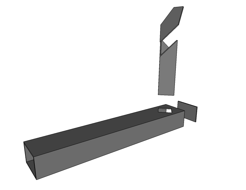
The feed is close to twice as large as the stub, csa-wise. It's also produced using a grinder with a thin cutting blade and a welder. A drawing of a size which is suitable for a 150 mm (6") system can be obtained here.
In contrast with the normal implementation this core version should be lit on top of the fuel pile at the back, known as "upside down firing". This method will deliver the best results.
This diagram represents a testrun using larger pieces of bone dry birch, lit on top. The start temperature of the heater itself happened to be moderately warm, start temperature in the chimney 30 ºC (86 ºF). The CO dropped at 18 minutes into the burn below 500 ppm and stayed down there for 58 minutes. The averages of this run: O2 13%, eff. 95.2%, CO 282 ppm, Tr 66.4 ºC (152 ºF). Mark the end level of CO is unusually low.
To conclude: the drawing of this core is available via this link.
5: Cast sidewinder, 7 parts
This is a variant of a batch box rocket where the riser is placed either left or right of the firebox. The design is developed by Adiel Shnior and Shilo Kinarty, two guys building rocket mass heaters in Israël. Max Edleson, a heater builder in the USA named it the "sidewinder". This is the name of a desert snake which moves by winding sideways over the sand.
As the riser is no longer directly in line with the combustion chamber, it is naturally no longer symmetrical. As a consequence, we need an extra mold to cast the combustion chamber, see below.
This design is similar to the earlier with a separate top piece, the most complicated mold is the back wall which has half of the lower part of the riser incorporated. It is possible to get away without making a second dedicated mold to cast the combustion chamber sides if a "fill piece" can be placed and secured into the mold prior to casting at the spot where the port should be. In this manner the one mold can cast both sides, one with an exit to the port due to the fill piece put into place before casting, the other without an exit. The top part of the firebox is the same as in the straight design and the other lower half of the riser is a relatively simple mold. For better understanding of the layout there's an exploded view below.
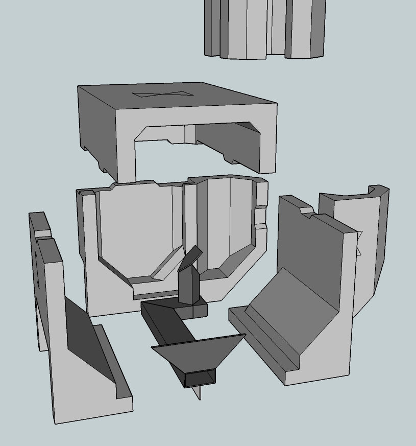
It looks very complicated, but with some careful inspection and thought it is entirely within a competent home handyman's ability. Although seemingly more complicated, these molds are assembled no differently than described in the "How to build" section. A coated plywood box with suitably formed pieces of extruded polystyrene (or other) to form the final shape.
To many this might be the first attempt to think with 'negative spaces' and how to demold the casting. I do believe it is within the capabilities of a good 'backyard tinkerer' so fear not. It might be a very good idea to test your molds with much cheaper materials, such as plaster of Paris, or even a weak cement sand mix, before (potentially) wasting the very expensive refractory castables on a mold that might need modification before the proper end result can be obtained.
As mentioned in the introduction, this is an open source project hence is available for commercial purposes (please read any attached conditions to that in the introduction section). If it is planned to make more than a few of these it is sensible to first make positive 'master molds' (that is, the actual shape itself, the 'positive') and from them make the rubber molds (ie these are now the 'negatives') to be used for the actual production run.
These second molds will need to be replaced periodically by recasting from the master mold. It seems to me a viable business opportunity to make and sell these castings along with good instructions on assembly and also the 'DIY actions' required to reach the final product. The total number of molds including the heat riser is five, possible to cast 7 parts in there. The drawing of this design is available through this link.
6: Brick sidewinder core
This design isn't difficult to build using fire bricks and a wet saw. Not more difficult than the straight batch rocket design, anyway. In order to make things a bit simpler the design size is a little bit enlarged, from 150 mm (6") to 160 mm (6.3"). By doing this, the firebox becomes also slightly larger so somewhat larger and thicker fuel could be loaded.
It would be sensible to keep the same depth as in the straight brick core version. Together with the riser no longer being at the back this would result in an installation depth of 486 mm using bricks this size. This would be a saving of 216 mm as compared to 702 mm of the straight core. The differences in firing behaviour are fairly small so this will be a good alternative. These sizes are all nominal, no thickness of the mortar between the bricks is taken into account.
The floor channel's vertical part is somewhat lengthened to accomodate the larger size of the riser and the port. Besides, this channel is constructed simpler as compared to the one in the casted sidewinder version, no 90 degree bend in it and the vertical part is placed a-symmetrical on the horizontal part in order to create sufficient distance to the port. On both sides of the vertical part there should be the same space as half the port width, measured perpendicular to the sides of the vertical channel, between this and the corners of the port.
Of course it is possible and also better to use the octagonal riser of the design 2:Brick core which will yield better firing results. Use this link to download the SketchUp drawing.
7: Another core layout
Between autumn of 2017 and the summer of 2018 quite a bit of experience has been gained with a layout consisting of a floor channel and a riser that is square instead of the more usual round or octagonal shape. It's performance is at least as good as a batchrocket with p-channel and round riser but has the accompanying advantage of a much easier construction - less cutting of bricks and a simpler layout, building should be easier. At times during this testing the back sweep, the ramp at the bottom rear of the riser, was left out (giving further simplicity) with equally excellent and encouraging results. (see under video for diagram)
In this layout, it is now only at the back of the riser below the level of the port that we have chamfered corners (watch for this in the video) resulting in a half-octagon that allows the double vortex (rams horns) to develop more easily.
The already published dimension tables are to be used with this design. That is to say a 150 mm design has a square riser 150mm*150mm and all of the remaining dimensions come from the spreadsheets and tables for a round 150 mm riser. Similarly for all other system sizes, so a batch rocket of size (X) has all of the dimensions for that system size (X) from the tables coupled with a square riser of that dimension (X*X). The round cross section riser is simply replaced with a square section riser with the side of the same dimension as the diameter of a round one. Please read about the consequences of a square riser as opposed to a round one in the "Building" chapter.
This design came about rather by accident, during a workshop on the Spanish island of Mallorca in November of 2017. The wet saw that had been hired was not capable of doing the 45 degree cuts to the accuracy we required, forcing me to try this method of construction. It was not as much of a stab in the dark as might be implied, my experience over the years had led me to suspect this method was entirely workable, and some separate experiments had strongly supported that suspicion. Perhaps a lucky set of circumstances. And it worked flawlessly straight out of the box so to speak, wet bricks and all. Here is a time lapse video of the entire build. Drawing of the build can be downloaded via this link.
Much of the further actual building and testing of the concept was done by Yasin Gach of France during other workshops and commercial builds. Recommended layout for this floor channel/riser combination is now like the drawing and picture. The drawing of the core can be downloaded here.
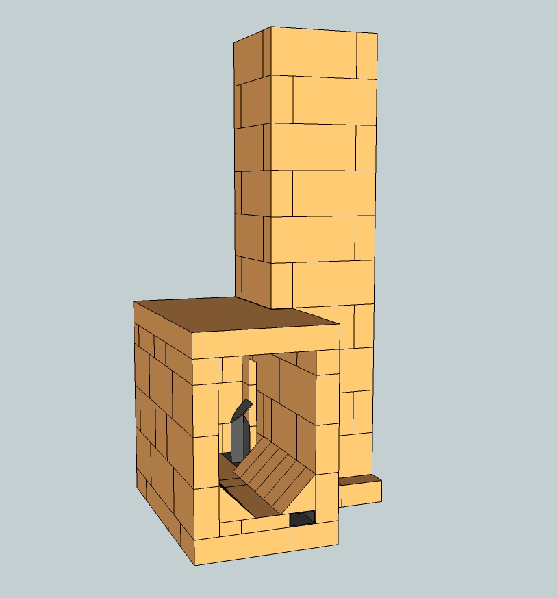
8: Double Shoebox Rocket: DSR 1, 2 and 3
Autumn 2021.
All previous designs are variants of the vertical riser, whether behind or beside the fire chamber. One disadvantage of this is the considerable installation height. A vertical riser, together with its minimal top gap, sets a fixed height for any method of extracting heat from the flue gases, which can be cumbersome in some applications. In the course of 2017 I began experimenting with a riser that lays horizontally on top of the fire chamber. The advantage is a lower installation height and because there is no riser behind it, the depth is approximately the same as with the sidewinder. The shape of the whole is reminiscent of two boxes on top of each other: the working title therefore became "double shoebox rocket". It never happened to come up with a better name so it stayed that way. This soon became an abbreviation: DSR, and Satamax Antone from France thought that could be an abbreviation of Désirée. Very romantic, because that name means "the long-awaited one".
At the moment there are three variants of the same concept.
Development of the first (DSR1) stopped in 2018, because it never led to a reliable design. As a free-standing structure with a meter of pipe on it, the DSR1 did well, very well in fact. But built into a few barrels and connected to a full chimney, it tended to burn harder and harder until all the fuel was used up. Not a big deal in itself, but during such a thermal overdrive large dark gray smoke billows came out of the chimney. With the current focus on reducing particulate matter and smoke nuisance, this is not something that would be appreciated by the neighbors.
Much of the DSR1 experimentation has been published on three forums: Ecologieforum, Donkey32 proboards and two links for the third forum Permies.com and Permies.com DSR cookstove.
All this is relevant to the development of the DSR3. That is why I have told the story here.
In the fall of 2018, development continued with the second variant: DSR2. This has resulted in a useful core. Many of the good qualities of the original batch rocket can be found in it.
This development has also been published as usual: Ecologieforum and Donkey.proboards.
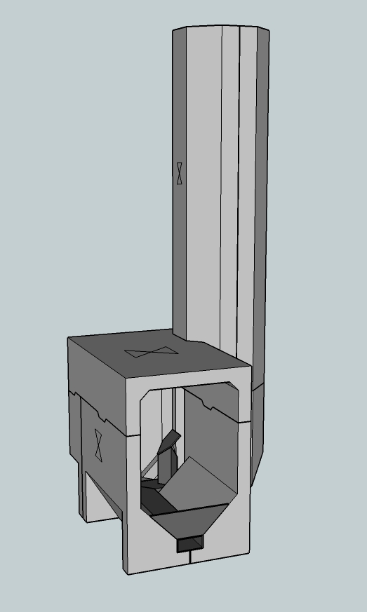
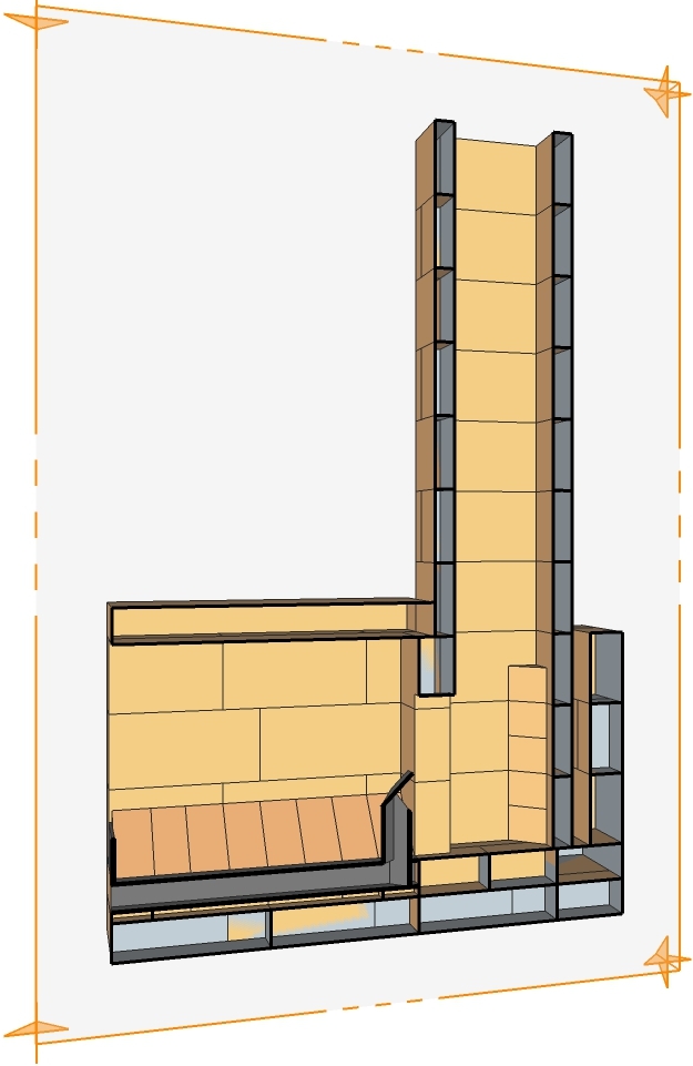
In short, this DSR2 core consists of a fire chamber with a short riser behind it, this is the first box. The proportions of this box are the same as those of the straight batch rocket, so the dimensions are in accordance with the well-known table and spreadsheet. On top of the first is a second box, the same width as the firebox below and with a height equal to the width. The total depth of both boxes is also the same, so all walls can be placed on top of those of the bottom box. A door can also be made in the top box, so that it can function as a (black) oven. The fire chamber has a normal port of the same size as in other batch rocket designs. The short square riser opens into the top box, which has a final exit in the form of a transverse slot relatively close to the front. Also in the top box, halfway along its length, a so-called “stumbling block” is dropped transversely beneath the ceiling.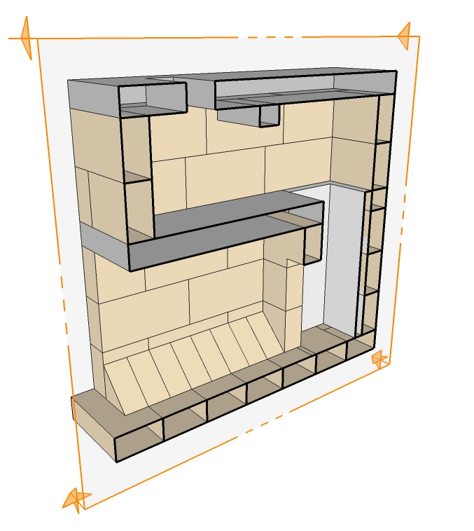
With a short chimney on top of the exit, this version works perfectly. However, an open version is not suitable for indoor use; a door in front with an air inlet is much safer. So far (autumn 2021) quite a bit of experience has been gained with this core. In the meantime, some principle drawings have also been made that show a few possibilities. One of them has a fully developed door and air inlet combination. All files have the SketchUp version 8 file format and can be downloaded here.
DSR2 closed, the cast version with door set and combined primary/secondary air inlet.
DSR2 open brick, the brick version, as shown above.
DSR2 open split, a version built of thin chamotte bricks with a box of ceramic fiberboard around it as a structural element.
DSR2 cast open, the cast version without door or secondary air inlet.
The version with secondary air inlet, here in the form of a floor channel, deviates somewhat from the other principle cross-sections. The fire chamber is slightly higher, to compensate for the thickness of the floor channel. Accordingly, the gate is also higher. All other sizes are the same.
There are two builds of a DSR2 core with a heated bench that I have worked on. The first is in Amayuelas, in the north of Spain. The exhaust is located low in the small bench on the left. The drawing can be downloaded via this link.
The second is in Gierle, south of Turnhout in Belgium. No exhaust is shown in this one either, it is placed low in the back wall of the right-hand bench, close to the bell. Download via this link.
Work in progress, more to come!