
")

")


 Batch Box Rocket by Peter van den Berg
is available under the Creative Commons Attribution-ShareAlike 4.0 International license
It has been decided to offer the information on this site free and without advertising. However, the provision of this information on this website does cost money which include hosting fees. Experiments which led to the results and the final designs presented on this website have also cost money. Including the purchase of a gas analyzer which need to be calibrated once a year in order to generate reliable results and being able to offer those to you.
Your donation is essential in order to continue this work and to maintain this site.

All heater cores are designed by Peter van den Berg, unless stated otherwise.
1: Brick core
A masonry firebox and riser is the simplest to produce, although fire bricks need to be cut. By using an optimized design this cutting could be minimal.
(read more)
P-channel
This duct supplies the secondary air in the original design. Simply constructed, it works solely due to the law of physics known as the Bernoulli principle.
(read more)
2: Brick core
The problem of the non-round riser of the brick core above is solved in this second design, the riser is now octagonal which is a better approximation to round. The layers are applied alternately on edge and flat in a reasonable running bond.
(read more)
3: Cast core
This is a firebox assembly together with the lower third of the heat riser in two separate parts. This one is built already quite often and works well but is vulnerable to cracking.
(read more)
4: Cast core
This is a recent design (2015) with the firebox divided into three parts. Instead of a p-channel there's a floor channel present.
(read more)
Floor channel
Also a secondary air supply but this one applies the air halfway in the height of the port. This duct lies on the floor of the firebox and recieves its air from the main air inlet.
(read more)
5: Cast core (sidewinder)
A design where the riser isn't situated behind the firebox but at the side instead, allowing a shallower depth.
(read more)
6: Brick sidewinder
A simpler way to build a one-off sidewinder as compared to making molds and cast the parts is building from firebricks. Unfortunately the number of bricks to be cut is quite substantial.
(read more)
7: A simpler core design
A combination of a square riser and a floor channel. Simpler to build, less cutting of bricks and still very good results.
(read more)
8: Double Shoebox Rocket
Variants that require a considerably smaller installation height. Compact, with a character all of its own.
(read more)
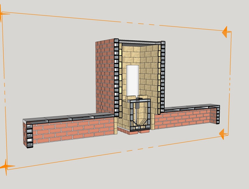
1: Straight brick core
Using a good layout and a suitable clay/sand mix this masonry version is an easy way to test these principles for yourself. This can be done outdoors, in a barn or shed, anywhere that is convenient. A word of warning, the riser will likely have flames shooting out of the top, so use chimney pipe to vent when tested in enclosed spaces. It is not 'only' a convenient test bed, it is more than suitable for permanent use as the core for a space heater (the clay sand mix allows for easy disassembly after testing). As will be described later, space heaters take advantage of the ultra clean burn provided by these combustion units and are able to capture and store the heat produced.
Of course it's sensible to build on stable footing, preferably insulating or using an intermediate insulation layer. The drawing in SketchUp 8 format of this design is available to download via this link. The internal shape of the riser is square, this is not as good as round, it will work but the shape isn't optimal. This version is suitable to build out of hard fire bricks. The layout of these bricks may need adjustment, this design is based on a brick size common in the Netherlands. Naturally, at least the riser should be surrounded by heat resistent insulation material. This isn't the case when this core is built using light weight insulating fire bricks. On the other hand, these are probably just a tad too vulnerable to abrasion to be used in the firebox.
P-channel
The steel rectangular duct on top of the firebox provides the secondary air supply. This part is commonly called the p-channel, short for Peter channel after its designer. Common mild steel or stainless steel is suitable material to manufacture this part. In this 150 mm (6") system a rectangular duct of 60x20x2 mm (2.36"x 0.8 " x 0.08") is being used.
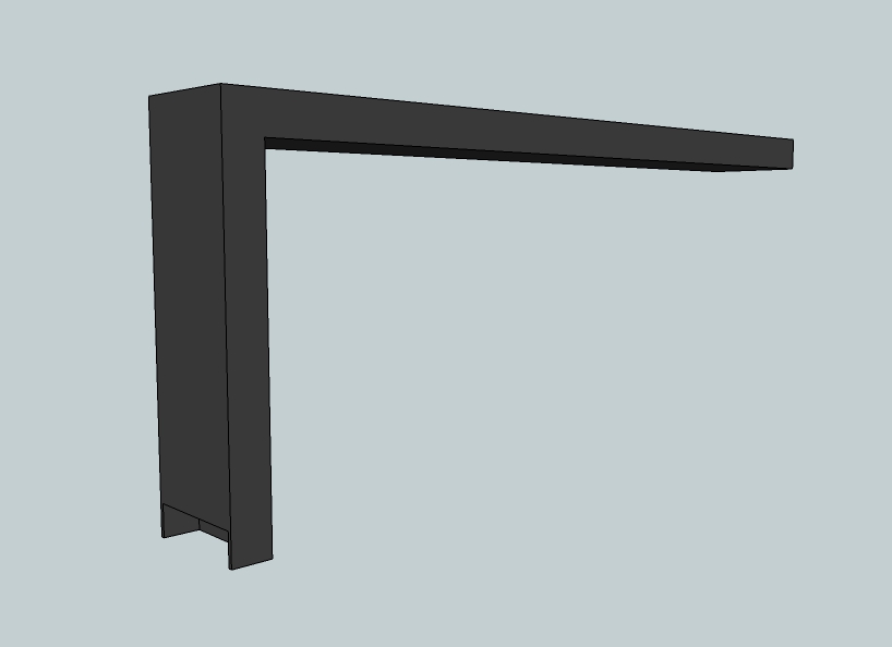
The downward hanging end stops a little lower than the top of the port, providing a small overhang. To keep things simple, this overhang is the same as the depth of the channel. At the back which is facing the riser a small piece is cut out to promote the suction of air. The same principle that causes the p-channel to work, Bernoulli's principle, means the pressure within the system is lower than that outside. Hence no smoke will escape the p-channel, indeed any other small cracks or the main air inlet itself. Conversely, if smoke does come out of the p-channel or main air inlet, then it means there is something wrong in the system.
This secondary air needs to be added to the stream in advance of the strong turbulence in the port and behind. Supplying air in the riser itself seems obvious but it won't work, mixing isn't powerful enough this way.
The duct is being cooled by the incoming air so the life expectancy of common steel is surprisingly long. Damage by corrosion in a space heater which has been used for two seasons is barely visible. So, it would be wise never to shut off the p-channel during operation. It is suspected a larger wall thickness of the duct could promote quicker corrosion because the steel can't shed heat as fast as the thinner material.
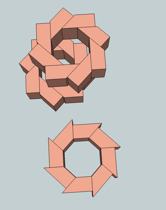
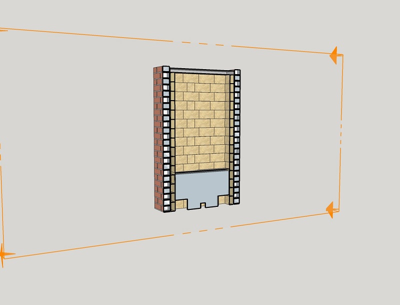
2: Straight brick core, octagon riser
The problem of the non round riser is solved in this next design, the riser is octagonal now which is a better approximation to round. The layers are applied alternately on edge and flat in a reasonable running bond. The smoother the riser inside the better, so it's rewarding to be very careful when building this part.
The octagon is a favorable shape because this way the double vortex will initiate earlier in the burn. The drawback of this shape is the higher mass. Such a disadvantage won't be in play when insulating fire bricks are used for this build. Even insulating material around the riser isn't necessary anymore, the bricks are insulating enough by themselves.
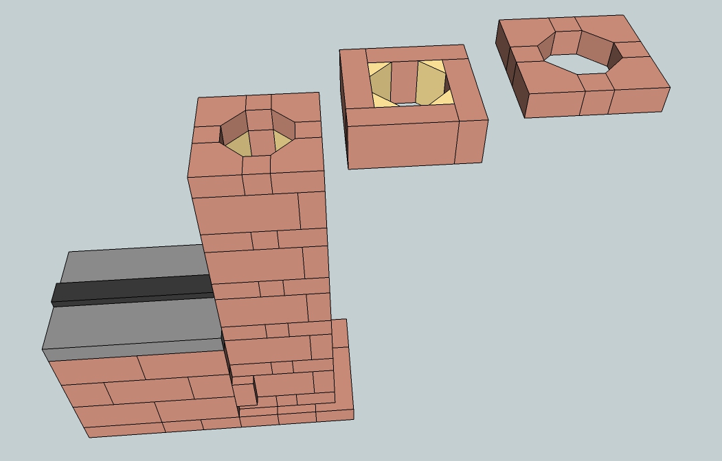
The small yellow triangles are in reality the same material, the different color is only there for easy visualisation. Construction of this core is different from the first brick design, the connection between firebox and riser is dissimilar. This drawing is available for download too, use this link.
Below are two other examples of how to make the riser octagonal out of normal brick sizes. Both use bricks that have been cut with a 45 degree angle to create equal sized "halves" to form an octagon shape. The lower one is simple but allows only one size of riser while the other allows the bricks to be adjusted to a slightly wider riser. A wider riser would mean the firebox and port should be wider as well, the scaling method still applies.
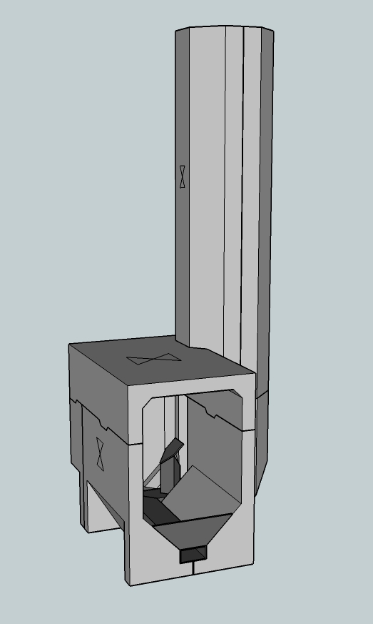
3: Straight cast core, 4 parts
This a tried and proven design with quite a few successful examples around the world. One conspicuous although not fatal flaw is the fact that this version is prone to cracks left and right in the firebox. The firebox will stay whole, after the cracks have appeared nothing much will happen later on. Probably the cracks themselves act as expansion joints, tension is released and the cracks won't grow anymore. Thickness of the walls are as thin as 30 mm (1.18") and where applicable fill pieces are used to economize on material. This isn't done to save money but to reduce the mass of the core. The less material in there, the sooner the thing is up to working temperature.
The part of the riser above the firebox is also split up in two parts which are identical so those could both be cast in the same mold.
The cross on the sides indicates which side is on top during casting. That side will remain relatively rough but that's of no consequence. Not only is the octagon a preferred shape (a very good approximation to round) it is also easily formed when building a mold. A table saw set to 45 degrees will cut all of the pieces required. Careful use of a hand held electric saw with a fence/guide will also serve if a table saw is not available.
This drawing is also free to use, downloadable via this link.
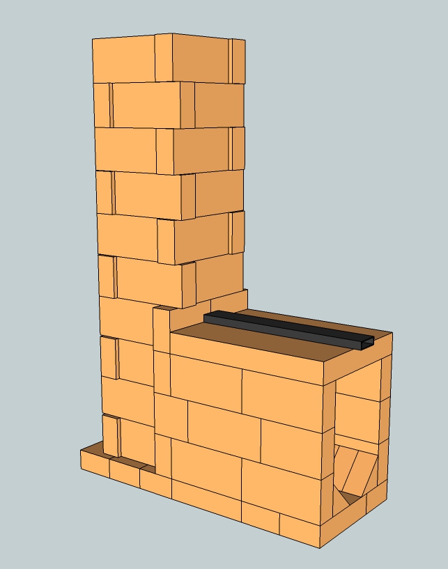
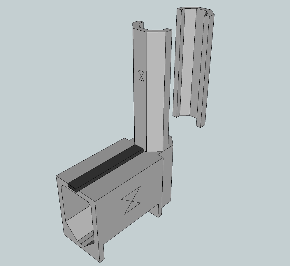
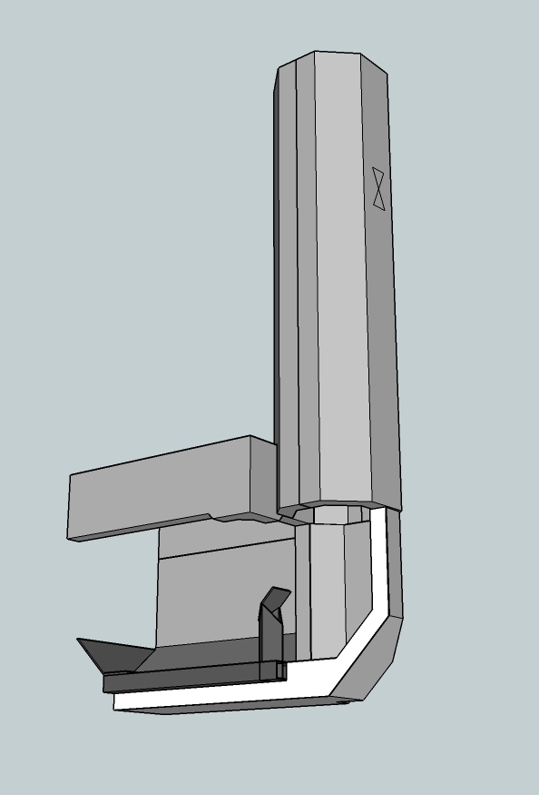
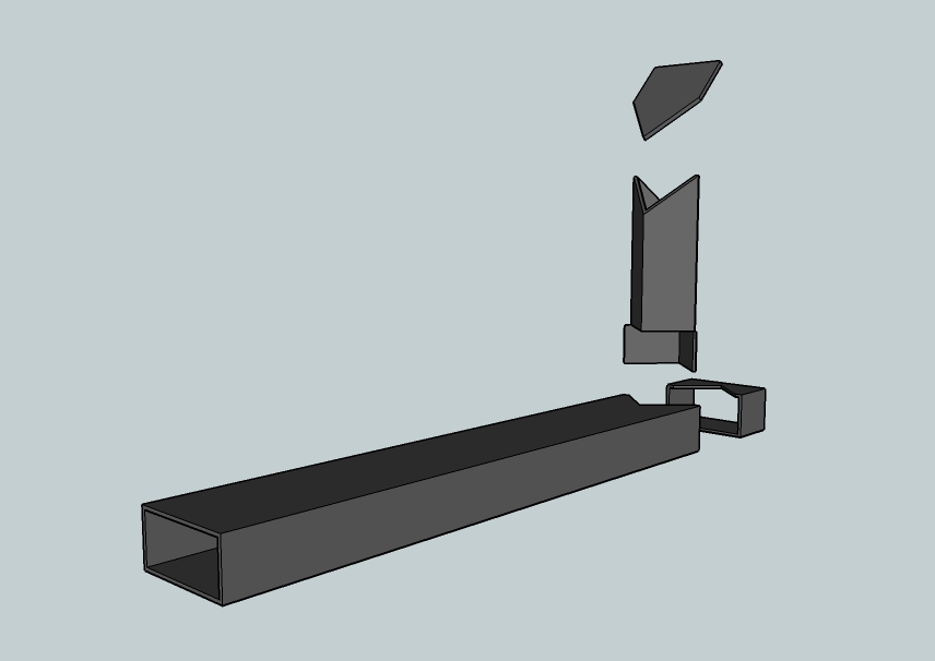
4: Straight cast core, 5 parts
This design is quite recent (2015) and has been in daily use for one winter without visible cracks. In my implementation the bottom rests on a support frame and the upper side is held together by cams and corresponding recesses in the top part. The picture below shows a slightly adapted drawing but is essentially the same as the one in my own heater.
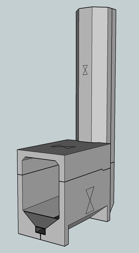
Naturally, the riser of this one need to be insulated from top to bottom as well. Construction is fairly simple, shown by the picture below.
Floor channel
This secondary air supply duct is an alternative to the p-channel, not to be used in the same heater. The construction and placement is quite different, it lies at the floor of the firebox in a trench and it is fed through the same inlet as the main air supply. It is called a floor channel and as such it is a variant of Matt Walker's pre-port tube but the vertical part is shorter, square and less wide. As a consequence, the tube is less of an obstruction inside the firebox.
On top of that the air is supplied halfway up the port which in turn keeps the double vortex low in the riser on average. This version is somewhat easier to produce than Matt's, the only tools used to produce this thing is a small grinder equipped with a cutting wheel and a welder. This floor channel is very easy to replace, an advantage as compared to the p-channel which can't be taken out unless the heater is opened up.
The channel is made out of normal 2 mm thick steel rectangular duct and has very little corrosion or deterioration after a year of daily use in a temperate marine winter. The explanation for the lack of corrosion is that the inside of the duct is cooled by the incoming air. And the duct itself is in an oxygen poor corner of the firebox while the burn is going on, steel won't corrode in the absence of oxygen.
So, this is one of the few steel parts inside the firebox which isn't destroyed in ten runs, durability is reasonable. My next channel will be made out of stainless steel 304, life time expectancy should be even better.
The burns during winter of 2015/2016 were entirely dedicated to get this air supply right, about 12 variants have been tested. The drawing shows a horizontal duct of 60x30x2 mm (2.36" x 1.18" x 0.08") , the vertical piece measures 35x35x2 mm (1.38"x 1.38" x 0.08"). The internal cross section area of the larger duct is about 1.5 times as large as the smaller one. This is not a coincidence, three sizes of the horizontal pipe are tested in several combinations with three vertical sizes. The duct of 60x30x2 is just as effective as a 60x40x2 item, as long as the inlet is larger than the exhaust of the channel. Using the steel ducts as drawn, the vertical part is 5.4% of the riser CSA and the horizontal part 8.25%. By keeping close to these percentages it is possible to calculate the dimensions for a larger or smaller batchrocket according to their larger or smaller riser CSA.
01/05/2019 A somewhat simpler construction together with a larger feed part and a higher stub, according to the latest findings. The air flow is optimized in such a way that the top half of the port recieves the majority of the secondary air stream.
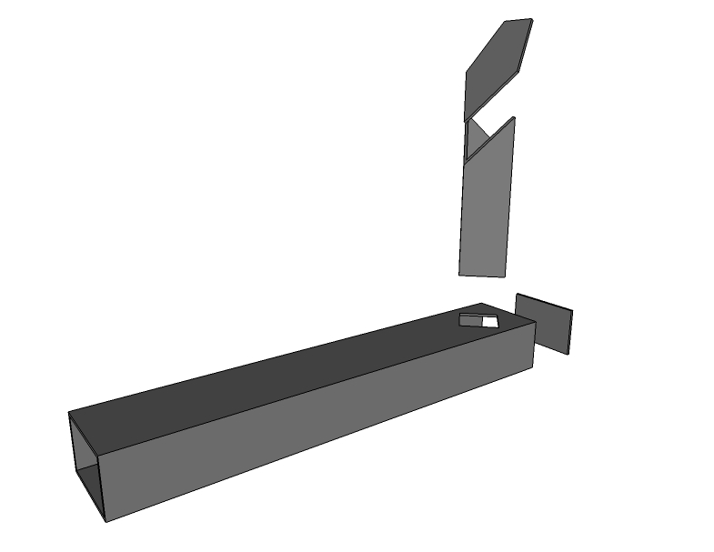
The feed is close to twice as large as the stub, csa-wise. It's also produced using a grinder with a thin cutting blade and a welder. A drawing of a size which is suitable for a 150 mm (6") system can be obtained here.
In contrast with the normal implementation this core version should be lit on top of the fuel pile at the back, known as "upside down firing". This method will deliver the best results.
This diagram represents a testrun using larger pieces of bone dry birch, lit on top. The start temperature of the heater itself happened to be moderately warm, start temperature in the chimney 30 ºC (86 ºF). The CO dropped at 18 minutes into the burn below 500 ppm and stayed down there for 58 minutes. The averages of this run: O2 13%, eff. 95.2%, CO 282 ppm, Tr 66.4 ºC (152 ºF). Mark the end level of CO is unusually low.
To conclude: the drawing of this core is available via this link.
5: Cast sidewinder, 7 parts
This is a variant of a batch box rocket where the riser is placed either left or right of the firebox. The design is developed by Adiel Shnior and Shilo Kinarty, two guys building rocket mass heaters in Israël. Max Edleson, a heater builder in the USA named it the "sidewinder". This is the name of a desert snake which moves by winding sideways over the sand.
As the riser is no longer directly in line with the combustion chamber, it is naturally no longer symmetrical. As a consequence, we need an extra mold to cast the combustion chamber, see below.
This design is similar to the earlier with a separate top piece, the most complicated mold is the back wall which has half of the lower part of the riser incorporated. It is possible to get away without making a second dedicated mold to cast the combustion chamber sides if a "fill piece" can be placed and secured into the mold prior to casting at the spot where the port should be. In this manner the one mold can cast both sides, one with an exit to the port due to the fill piece put into place before casting, the other without an exit. The top part of the firebox is the same as in the straight design and the other lower half of the riser is a relatively simple mold. For better understanding of the layout there's an exploded view below.
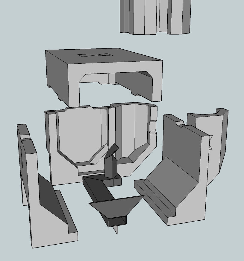
It looks very complicated, but with some careful inspection and thought it is entirely within a competent home handyman's ability. Although seemingly more complicated, these molds are assembled no differently than described in the "How to build" section. A coated plywood box with suitably formed pieces of extruded polystyrene (or other) to form the final shape.
To many this might be the first attempt to think with 'negative spaces' and how to demold the casting. I do believe it is within the capabilities of a good 'backyard tinkerer' so fear not. It might be a very good idea to test your molds with much cheaper materials, such as plaster of Paris, or even a weak cement sand mix, before (potentially) wasting the very expensive refractory castables on a mold that might need modification before the proper end result can be obtained.
As mentioned in the introduction, this is an open source project hence is available for commercial purposes (please read any attached conditions to that in the introduction section). If it is planned to make more than a few of these it is sensible to first make positive 'master molds' (that is, the actual shape itself, the 'positive') and from them make the rubber molds (ie these are now the 'negatives') to be used for the actual production run.
These second molds will need to be replaced periodically by recasting from the master mold. It seems to me a viable business opportunity to make and sell these castings along with good instructions on assembly and also the 'DIY actions' required to reach the final product. The total number of molds including the heat riser is five, possible to cast 7 parts in there. The drawing of this design is available through this link.
6: Brick sidewinder core
This design isn't difficult to build using fire bricks and a wet saw. Not more difficult than the straight batch rocket design, anyway. In order to make things a bit simpler the design size is a little bit enlarged, from 150 mm (6") to 160 mm (6.3"). By doing this, the firebox becomes also slightly larger so somewhat larger and thicker fuel could be loaded.
It would be sensible to keep the same depth as in the straight brick core version. Together with the riser no longer being at the back this would result in an installation depth of 486 mm using bricks this size. This would be a saving of 216 mm as compared to 702 mm of the straight core. The differences in firing behaviour are fairly small so this will be a good alternative. These sizes are all nominal, no thickness of the mortar between the bricks is taken into account.
The floor channel's vertical part is somewhat lengthened to accomodate the larger size of the riser and the port. Besides, this channel is constructed simpler as compared to the one in the casted sidewinder version, no 90 degree bend in it and the vertical part is placed a-symmetrical on the horizontal part in order to create sufficient distance to the port. On both sides of the vertical part there should be the same space as half the port width, measured perpendicular to the sides of the vertical channel, between this and the corners of the port.
Of course it is possible and also better to use the octagonal riser of the design 2:Brick core which will yield better firing results. Use this link to download the SketchUp drawing.
7: Another core layout
Between autumn of 2017 and the summer of 2018 quite a bit of experience has been gained with a layout consisting of a floor channel and a riser that is square instead of the more usual round or octagonal shape. It's performance is at least as good as a batchrocket with p-channel and round riser but has the accompanying advantage of a much easier construction - less cutting of bricks and a simpler layout, building should be easier. At times during this testing the back sweep, the ramp at the bottom rear of the riser, was left out (giving further simplicity) with equally excellent and encouraging results. (see under video for diagram)
In this layout, it is now only at the back of the riser below the level of the port that we have chamfered corners (watch for this in the video) resulting in a half-octagon that allows the double vortex (rams horns) to develop more easily.
The already published dimension tables are to be used with this design. That is to say a 150 mm design has a square riser 150mm*150mm and all of the remaining dimensions come from the spreadsheets and tables for a round 150 mm riser. Similarly for all other system sizes, so a batch rocket of size (X) has all of the dimensions for that system size (X) from the tables coupled with a square riser of that dimension (X*X). The round cross section riser is simply replaced with a square section riser with the side of the same dimension as the diameter of a round one. Please read about the consequences of a square riser as opposed to a round one in the "Building" chapter.
This design came about rather by accident, during a workshop on the Spanish island of Mallorca in November of 2017. The wet saw that had been hired was not capable of doing the 45 degree cuts to the accuracy we required, forcing me to try this method of construction. It was not as much of a stab in the dark as might be implied, my experience over the years had led me to suspect this method was entirely workable, and some separate experiments had strongly supported that suspicion. Perhaps a lucky set of circumstances. And it worked flawlessly straight out of the box so to speak, wet bricks and all. Here is a time lapse video of the entire build. Drawing of the build can be downloaded via this link.
Much of the further actual building and testing of the concept was done by Yasin Gach of France during other workshops and commercial builds. Recommended layout for this floor channel/riser combination is now like the drawing and picture. The drawing of the core can be downloaded here.
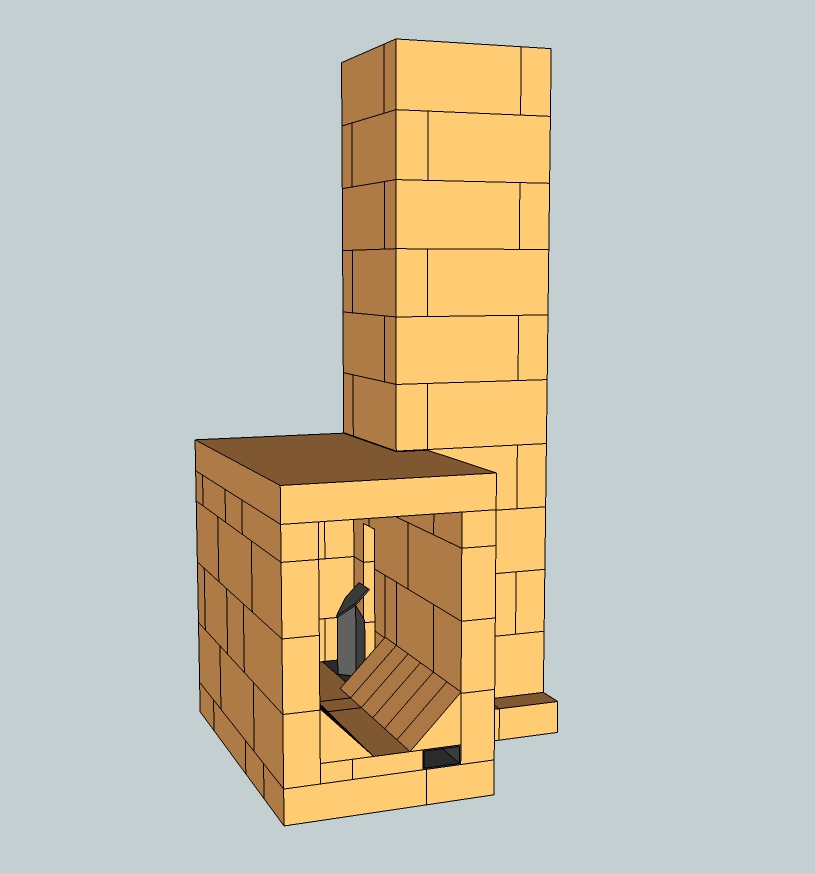
8: Double Shoebox Rocket: DSR 1, 2 and 3
Autumn 2021.
All previous designs are variants of the vertical riser, whether behind or beside the fire chamber. One disadvantage of this is the considerable installation height. A vertical riser, together with its minimal top gap, sets a fixed height for any method of extracting heat from the flue gases, which can be cumbersome in some applications. In the course of 2017 I began experimenting with a riser that lays horizontally on top of the fire chamber. The advantage is a lower installation height and because there is no riser behind it, the depth is approximately the same as with the sidewinder. The shape of the whole is reminiscent of two boxes on top of each other: the working title therefore became "double shoebox rocket". It never happened to come up with a better name so it stayed that way. This soon became an abbreviation: DSR, and Satamax Antone from France thought that could be an abbreviation of Désirée. Very romantic, because that name means "the long-awaited one".
At the moment there are three variants of the same concept.
Development of the first (DSR1) stopped in 2018, because it never led to a reliable design. As a free-standing structure with a meter of pipe on it, the DSR1 did well, very well in fact. But built into a few barrels and connected to a full chimney, it tended to burn harder and harder until all the fuel was used up. Not a big deal in itself, but during such a thermal overdrive large dark gray smoke billows came out of the chimney. With the current focus on reducing particulate matter and smoke nuisance, this is not something that would be appreciated by the neighbors.
Much of the DSR1 experimentation has been published on three forums: Ecologieforum, Donkey32 proboards and two links for the third forum Permies.com and Permies.com DSR cookstove.
All this is relevant to the development of the DSR3. That is why I have told the story here.
In the fall of 2018, development continued with the second variant: DSR2. This has resulted in a useful core. Many of the good qualities of the original batch rocket can be found in it.
This development has also been published as usual: Ecologieforum and Donkey.proboards.
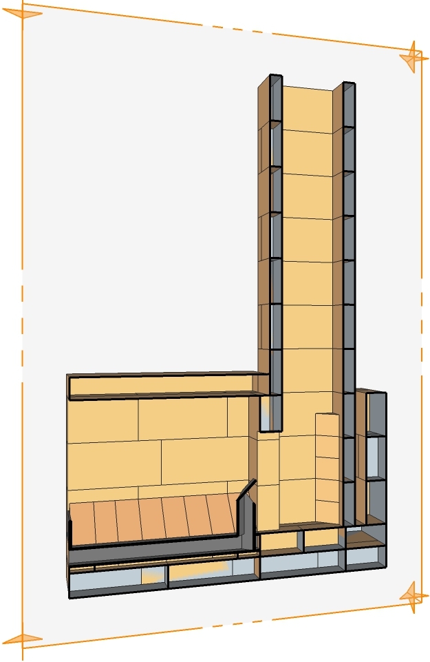
In short, this DSR2 core consists of a fire chamber with a short riser behind it, this is the first box. The proportions of this box are the same as those of the straight batch rocket, so the dimensions are in accordance with the well-known table and spreadsheet. On top of the first is a second box, the same width as the firebox below and with a height equal to the width. The total depth of both boxes is also the same, so all walls can be placed on top of those of the bottom box. A door can also be made in the top box, so that it can function as a (black) oven. The fire chamber has a normal port of the same size as in other batch rocket designs. The short square riser opens into the top box, which has a final exit in the form of a transverse slot relatively close to the front. Also in the top box, halfway along its length, a so-called “stumbling block” is dropped transversely beneath the ceiling.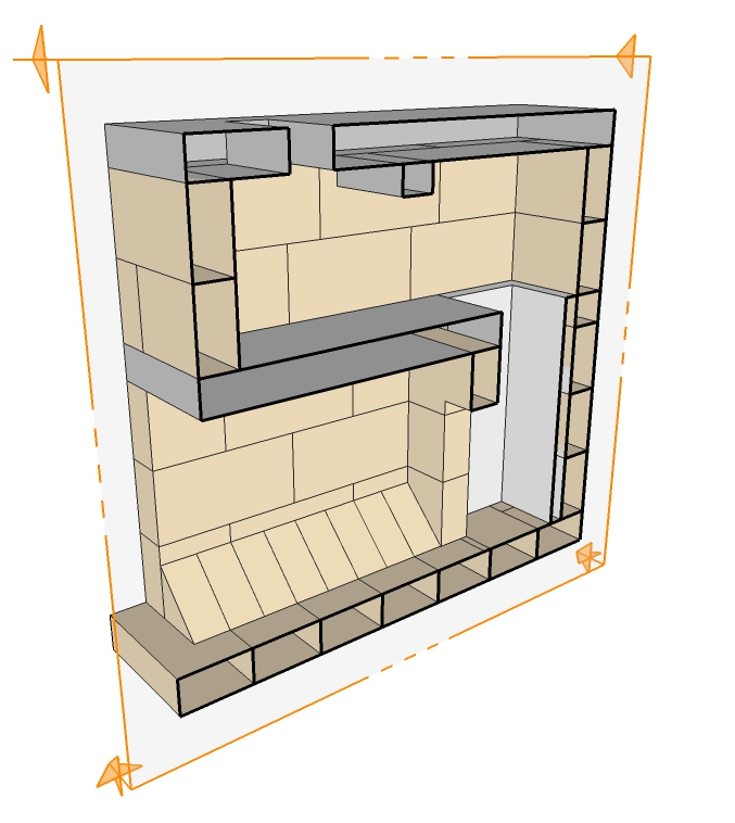
With a short chimney on top of the exit, this version works perfectly. However, an open version is not suitable for indoor use; a door in front with an air inlet is much safer. So far (autumn 2021) quite a bit of experience has been gained with this core. In the meantime, some principle drawings have also been made that show a few possibilities. One of them has a fully developed door and air inlet combination. All files have the SketchUp version 8 file format and can be downloaded here.
DSR2 closed, the cast version with door set and combined primary/secondary air inlet.
DSR2 open brick, the brick version, as shown above.
DSR2 open split, a version built of thin chamotte bricks with a box of ceramic fiberboard around it as a structural element.
DSR2 cast open, the cast version without door or secondary air inlet.
The version with secondary air inlet, here in the form of a floor channel, deviates somewhat from the other principle cross-sections. The fire chamber is slightly higher, to compensate for the thickness of the floor channel. Accordingly, the gate is also higher. All other sizes are the same.
There are two builds of a DSR2 core with a heated bench that I have worked on. The first is in Amayuelas, in the north of Spain. The exhaust is located low in the small bench on the left. The drawing can be downloaded via this link.
The second is in Gierle, south of Turnhout in Belgium. No exhaust is shown in this one either, it is placed low in the back wall of the right-hand bench, close to the bell. Download via this link.
Work in progress, more to come!
Preface
In this chapter will be shown what is actually done to create a complete space heater using the combustion cores introduced previously. The concepts will be explained as we go, but not all of these will necessarily have accompanying photographs if copyright restrictions are in place. But measurements and sketches could be converted to 3D drawings in SketchUp format, by the builder of the heater or by me in due time. This way, sufficient information will be available to people who like to build one or more of the designs for their own purposes.
The true magic of this technology is realised once we couple the clean burn technology of the combustion unit/s covered previously with effective ways of harvesting that very clean, smokeless heat. This can be done in a number of different ways that allow us to have different applications. We can build a space heater for applications that require 'heat on demand', for example a workshop that is only occupied during working hours. This type has very little mass but very high radiant output. For other cases (eg in a house) where long term 'constant heating' is needed we use much more mass that provides a lot of heat storage. These different approaches will be covered in this section.
All described variants are designed and/or built by Peter van den Berg, unless stated otherwise.
Only open source designs and descriptions will be included on this site, whether for people's private use or commercially. The Creative Commons license Attribution and ShareAlike is allowed, the GPLv3 public license is also possible as an alternative, one-way compatible with the CC license mentioned here.
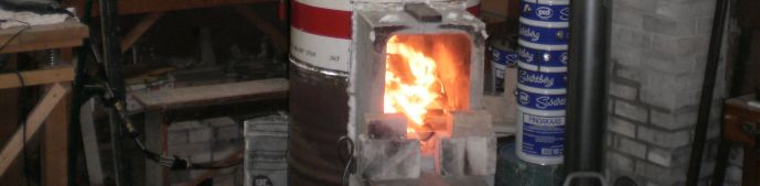
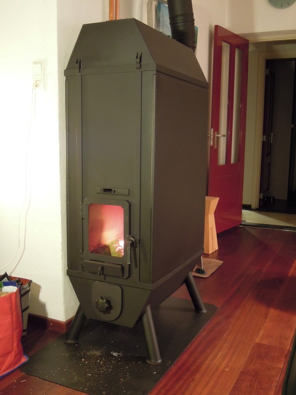
Workshop heater
Consisting of three oil barrels and a cast batch box rocket core. The core itself weighs 60 kg (132 lbs) but as the three steel oil barrels have very little mass there is little delay to the heat output of the core, basically instant heat.
(read more)
Bell with two benches
This was built during a workshop so not as a permanent construction by a complete team in a little more than 3 days. A very interesting build, it showed outstanding performance.
(read more)
Bell heater, cast construction
A 2015 design and build of a heater which is entirely dry stacked out of cast parts.
(read more)
Central heating boiler
Also a design from 2015, the whole of it is made of a lot of stainless steel, fire brick boards and split fire bricks. It burns clean and hot, the unpressurized storage is heated up with it and in turn the in-floor heating is fed with warm water.
(read more)
Pizza oven / pool heater
A third 2015 design, a batch rocket driving a pizza oven, warming the terrace and heating the swimming pool. Not for the fainthearted, but a very rewarding build for Tom De Smedt.
(read more)
Open batch rocket systems
These systems are built and run without a door or secondary air intake.
(read more)
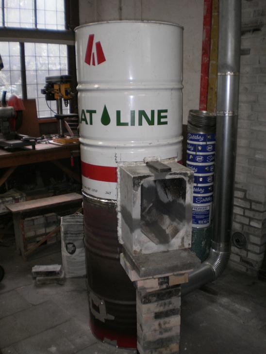
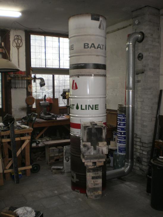
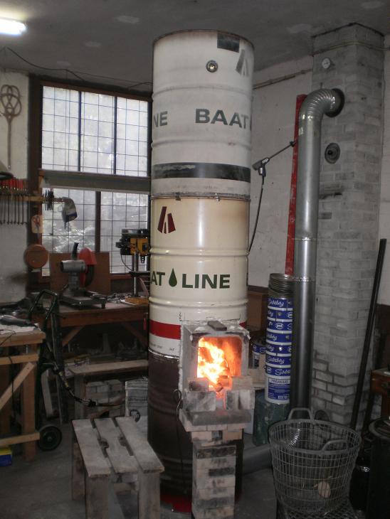
Three barrel batch rocket
During winter of 2013/2014 this heater functioned as the focal point of my old workshop. It is built as a 150 mm (6") riser diameter system, the same size as the chimney pipe. The whole of the heat extractor side consists of three barrels on top of each other, forming together a single cylinder. The top and bottom lid of the middle barrel are both cut out. The lower barrel is open at the top and the top one is open at the bottom. Leave about 25 mm (1") around the perimeter when cutting out the lids, the added strength keeps the barrels circular. The batch rocket combustion core is a cast item which is protruding out of the side of the barrel cylinder. See the diagram below.
The masonry column in the lower barrel is resting directly on the floor, it doesn't rest on the bottom of the barrel. A square opening in the bottom cut for the size of the column allows that to happen. A flange is bent and hammered on all four sides of the opening, leaving a gap between the brick and steel which is stuffed with superwool to seal it off. This way, both the barrel and the column rest on the floor independently. Another opening is cut out and flanged to allow the core to stick out.
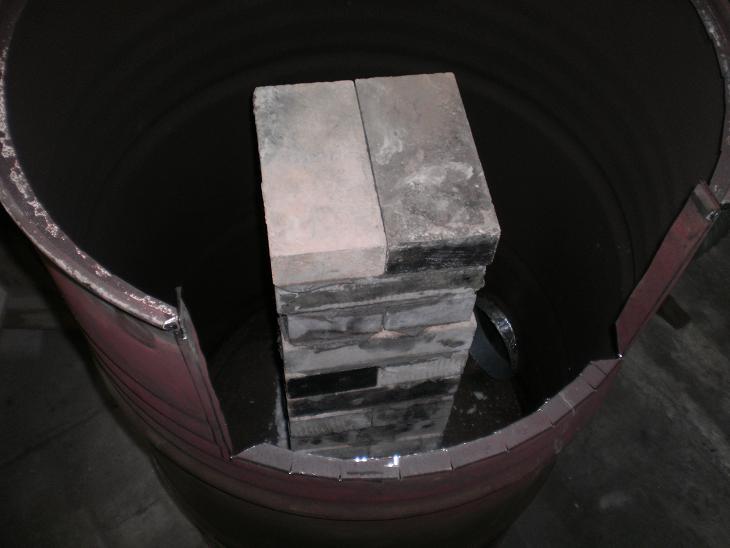
The core doesn't rest directly on the bottom flange, the internal masonry column and the external masonry support (see diagram just above) are sized so that the cast core is elevated about 8 mm (0.315") above the flange. A strip of superwool is glued (heat resistant stove caulk) to the flange which provides the seal. The riser isn't located exactly in the middle of the barrel so the firebox isn't protruding out as much.
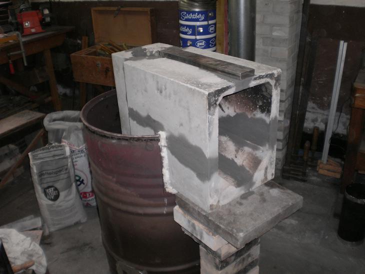
The gaps between the side of the firebox and the flanges are stuffed with superwool as well, as is clearly visible. There's another cut out in the second barrel plus a small one to give room for the p-channel. Flanges are bent/hammered all around and the gaps filled with the same sealant.
Next step is the placement of the riser, I don't have a picture of this, regrettably. A vacuum formed superwool duct, common in the metallurgic industry, is used as the riser in this heater. In the industry this type of duct is used to pour molten metal through to fill molds. Google "riser sleeve" or use this link.
The final step is preparing and placing of the third barrel. The rims are sealed with aluminum tape, this won't last forever but it is in full view so it's visible and easy to replace once it is worn out. The gas flow internally does not hit the rims of the barrel as such, the one inch around the rim that was left when the top and/or bottom of the barrels were removed causes the hot gas to bend around them and so the rims where the aluminium tape is used to seal the barrels always remain several tens of degrees cooler than the rest of the barrel.
The piping hot gases are spewn upward in the cylinder and need to go down to get to the only exhaust opening close to the floor. This exhaust is situated even lower than the firebox itself, which is around 500 mm (1'8"). As such, this barrel tower is acting like a bell heat exchanger as described in the "Bell theory" article. In addition to it acting like a larger bell due to the height of the combustion core, it makes for very easy and less streneous feeding of the fire than having to bend down and kneel to put the wood in.
To prevent having a restriction for the gases to access the exhaust opening (a common mistake and one of the first points to check in a poorly performing heater) the pipe is mounted about 100 mm (4") from the floor. Making a larger hole of 200 mm (8") is another way to help avoid any restrictions. In combination with a 200 to 150 mm (8" to 6") reducer to the diameter of the chimney pipe.
During the top of the burn the temperature of the uppermost barrel can easily reach 200 ºC (392 ºF) in this situation. So it would be sensible to keep combustible materials well away from the heater. Indeed when constructed in this manner treat it as a "normal combustion heater" and apply any and all codes applicable to the installation of such metal boxes.
I did not ever get around to making a door for this variant, a separate sheet of Robax heat resistant glass is used instead plus a couple of firebricks to shape the air inlet. Of course a door can be made if so desired. The chimney stack is straight, uninsulated masonry and 8.5 m (27.9') high, measured from the point where the pipe is inserted through the brickwork. Here is a low quality video showing in steps the burn's progress.
And last but not least: the report on the Rocket Stoves Forum dating from October 2013 about this subject.
No 3D drawing avaiable, sorry.
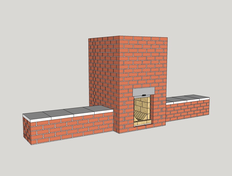
Bell with dead-end benches
This mass heater was built during the 2015 Annual Meeting of members and interested parties of the Masonry Heater Association of North America. This organisation of heater masons invests a lot of effort in making clear to governmental parties that their heaters are among the cleanest in the United States and Canada. Other activities are educating the members and providing standard designs, so in that respect they embrace the open source ideal shared by this website.
The main bell is drawn as a double skin design but during the (6!) workshops plus several mini-clinics and demonstration projects it turned out that the fire bricks were in short supply. In response to that problem the layout was altered to a complete single skin build, only the top half of the main bell was built out of fire brick in order to cope with the expected high temperatures. In North America, normally the masonry heaters are built as double skin, the inner skin entirely out of fire bricks. We skipped that layout during this workshop, the goal was to demonstrate a proof of concept for the MHA members, a bell heat extractor married to a batch box rocket core. It turned out to be quite a success, the thing burned really clean and the benches heated up without a hiccup, right out of the box so to speak.
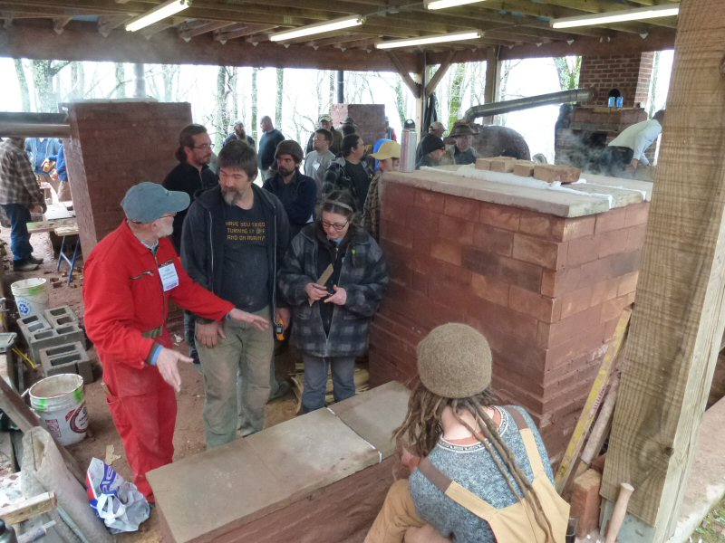
A vacuum formed superwool cylinder of 200 mm (8") diameter was used for a riser, the benches are drawn as single skin and the main bell double skin. A number of the MHA members found it strange the benches were built as dead ends in opposite directions. Doing it this way, it would be impossible for the exhaust gases to stream through in one, let alone both of them. The next picture shows the heater during the curing stage, the steam is coming off as lazy clouds. The top of the pictured bench already shows lighter spots. The end of the bench is still wet being completed last, less than an hour before lighting first fire.
There are a few tricks in this construction in order to get the hot gases to enter the benches, stream along the top of the benches and cool, and make their way back to the main bell to the exit located at the bottom. This mechanism relies on a principle of physics, the fact that hot gases are lighter because they have expanded. This is called the buoyancy of gases, driven by gravity and is the way a bell system works. Hot gases tend to rise and colder gases descend, to the exit. See also Bell Theory.
From this cut-away it can be seen that the opening between the main bell and the benches have no obstructions, the interior of the bench is carried through straight into the bell itself. In fact, this means that the benches are actually simply a continuation of the bell and form a single, larger bell with heat distribution sculpted to satisfy a new set of demands. Another illustration of the versatility of the bell concept. As covered in the Bell theory section, we can see that as the gases enter from the bell into the benches they enter a *much larger volume* and so slow down greatly, rise to the top, shed heat and make their way to the exit.
So there's a lot more time to transfer its heat. Naturally the main bell is the first to receive the gases, indeed the hottest gases, and so is the first to heat up. They then cool and make their way to the benches. So it is to be expected that the bench warms up after the bell, and in this construction that time delay was just 20 minutes. If the bell had been made of a double skin of bricks according to the drawing, then the benches would have been the first to warm.
The placement of the exhaust opening to the chimney stack is very important in this design, as in any bell design. As this design has benches attached to it (absent from the previous examples shown) thought needs to be given to how we get the hot gases into the benches and not 'short circuit to the exit flue' beforehand. The drawing below shows how it was achieved. A fireproof baffle board (in this case calcium silicate) is placed off the rear wall of the main bell and capped off at the top, see 3D drawing how this is done. Not seen in the picture below is the exit flue, 'hidden' behind the baffle plate. The circumference of this baffle board multiplied by the distance between it and the rear wall of the bell should be much larger than the cross sectional area of the flue. This is to ensure we do not have a restriction to the easy flow of gases into the flue. The openings cut into the baffle (as seen below) are also of a size much larger in area than the cross section of the flue. Again, we do not want restrictions to the gases. There is no 'opening' at the top of the baffle board, we do not want access to the exit flue until after they have opened into the benches. Note that the cutouts in the baffle are well below the level of the benches.
This baffle plate has helped us to achieve all we want from a bell. As the gases can ONLY reach the exit flue by entering behind the baffle plate from the bottom, only the coldest gases escape. To reach that opening the gases must have had to enter the benches and cool. We can also now see how "dead end benches" that initially baffled some of the attendees are so effective. It should also be clear that a baffle board is not the only solution, it happened to be the quickest and easiest way to do it during a "time starved" week. All that is needed is that the gases reach and warm the benches before exiting the flue, so it could be done with a shallow and wide opening at the bottom of the rear wall of the bell which leads to the vertical stack by means of a funnel shaped brickwork.
Large North American masonry heaters usually have a "bypass valve" incorporated. This is a steel or cast iron plate which is mounted in such a place in the heater that when it is opened by turning or sliding out, the hot exhaust gases are allowed to enter the chimney directly by a shortcut. This is a way to heat up the chimney stack before the masonry mass is warmed up so the chimney draw is initiated beforehand. Its main drawback is it complicates the construction and introduces a weak part in the heater which shouldn't be there in my opinion.
Still, it can be very handy when a cold heater needs to be lit in the depth of winter in an icy cold house. When one thinks such a bypass is desirable in this design, such a valve could be mounted in the area of the baffle board. Preferably not at the top of the bell which is the hottest area where a steel bypass valve could become warped or destroyed in time. The bypass valve shouldn't be confused with a 100% closing flue damper which can be very dangerous when there are still some glowing coals under the ash. Carbon monoxide can't be seen or smelled and it will kill people in their sleep when leaked into the house. A 100% closing door is a much better alternative and in addition to that, a CO detector is actually an indispensable safety measure.
The MHA meeting was a memorable event, with a couple of prominent names participating in the Rocket Heater team. Lasse Holmes, the creator of the batch rocket idea, Leslie Jackson, co-author of the "Rocket Mass Heaters" book and Kirk "Donkey" Mobert, creator of the first dedicated Rocket Mass Heater Forum. The photo below shows Lasse and Leslie dancing in front of the heater (or around the fire?). Just as an aside, the batch rocket heater here produces less smoke than can be seen in the picture.
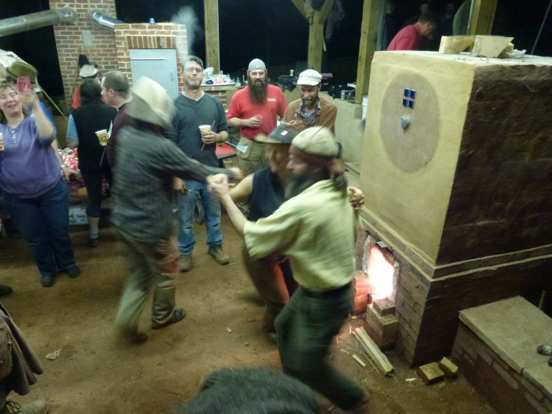
The two action pictures are copyright MHA, for more pictures commented by MHA's Norbert Senf and myself see the photo report of the MHA of this workshop. The 3D drawing of the complete heater is available through this link.
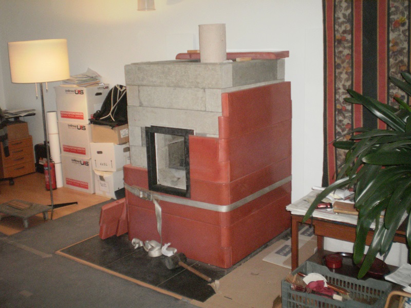
Bell heater entirely of cast parts
This is a batch rocket variant designed and built in 2015, consisting entirely of cast refractory parts. In such a project the financial investment in molds is very high. So much thought was put into devising a way to use as few unique parts as possible, thereby cutting down on the number of unique molds. As can be seen there are just a few parts repeated many times, the same few molds being used over and over as required. The finished external dimensions of the heater are 98 x 98 x 210 cm (3.22" x 3.22" x 82.7"), and all up it weighs in at a little more than 2000 kg (2.2 US tons).
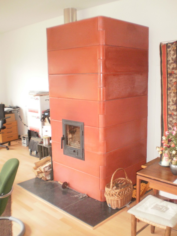
The outer finished face is made of specially ordered castable refractory in a terracotta colour, and consists of 28 identical parts which interlock with each other (for those counting in the picture- a good way to conceptually grasp it, the last seven pieces form the rear wall behind, in other words four walls of seven pieces each). The interlocking dovetails are seen at the corners, showing how the use of the same shape placed 'up and down' alternately manage to interlock with each other.
An added benefit of interlocking shapes like this is that it makes the construction easier as each piece is an easily handled and assembled part. A close look at the dovetails in the picture shows the slight, but important, angle they are cast at. This ensures that they lock together tightly, indeed force the dovetails to close. Not seen are "ball and dimple" locating pins that locate and secure each layer to the other layer. Knowing that, and referring to the picture it is clear that each layer is locked together as a unit by the wedge action of the dovetails, and each separate layer is locked to the next by the "ball and dimple" pins. All this allows gravity to do the job of holding it all together, they are not glued, mortared or fastened in any way. For full and complete details see the SketchUp drawing of this project, there's a link provided at the end of this article.
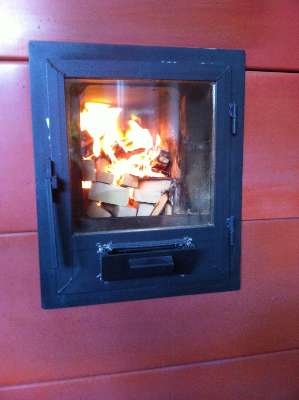
The door is made of steel T-profiles and hinges in a frame made of steel U-profiles with the open side facing outwards all around. That allows the outer skin pieces to fit into the open U which then supports and locks the door frame into place. (This can be seen more clearly in another photo below.) A simple tilting valve without hinges is mounted in the door which provides for the primary as well as the secondary air supply.
The firebox is identical to the description of "4: Cast core" in the chapter "Designs" and consists of 3 separate and different parts. The bottom left and right parts together form the port and base of the riser and the third part completes the combustion chamber when placed on the bottom pair. See assembled construction picture later. The top part locks into the locating lugs seen below.
The core rests on a welded steel frame incorporating adjustable bolts in three directions to obtain correct and secure placement inside the bell. This frame is also holding the left and right halves together by force of gravity (again). Both halves are supported by the frame's left and right outer ridges but not in the middle. As a consequence, both parts have the tendency to fall in each others' direction so the vertical seam will be held closed at all times. Note the steel frame doesn't support the core all of the way to the front, a small section of the core in unsupported by this frame. This will be explained later.
The upper part of the riser consists of a vacuum formed superwool circular tube which rests freely on the core base only held in place by a couple of short centering pins. Done in the most simple way: a couple of small holes drilled in the refractory and a couple of shortened nails inserted.
The internal wall of the bell is built out of two different blocks, repeated 24 times each (naturally a slight modification to the exact duplication of these two parts occurs where the exit flue and firebox appear, other than that they are, like the outer skin, a simple repetition of parts). Note the tongue and groove seen in the picture, and careful inspection will show the tongue and groove exists at the ends of the pieces as well.
One row consists of 4 parts and is 150 mm (5.9") high and 120 mm (4.7") thick. Every row is turned a quarter horizontally relative to the previous one, thereby locking each other in place. The rows are sealed with adhesive braided glass tape 10 mm wide and 4 mm thick (0.39"x 0.157") stuck to the tongue side. The weight of the parts will press the seal down to half the original thickness. The same goes for the vertical ends, tape on the tongue and pressure is applied to compress the tape and lower the part into place as the photograph shows. Note the groove is 2 mm deeper than the tongue is high, each block is resting on the sides, not on the tongue.
The exit hole to the chimney in this build is situated low at the left rear side. Thanks to the fact that this is a bell construction it doesn't matter where at the perimeter the exhaust is placed. To avoid a restriction due to the placement close to the floor and the inner corner the hole is shaped as a funnel. The opening inside is 250 mm (10"), reducing to 150 mm (6") in the thickness of the material. This way, there's plenty of space for the exhaust gases to stream into the exit opening.
The size of the opening for the combustion chamber in the inner skin is determined by the inner dimensions of the firebox/combustion unit. The front end of the firebox walls fits snugly in a rabbet of the inner skin. In this way, the front of the firebox is supported by the inner wall, the rear of the combustion core is supported by the adjustable metal frame pictured earlier. The perimeter of the firebox opening is sealed with superwool in the inner skin's rabbet/groove.

The left and right sides of the inner skin's opening are chamfered at a 45 degrees angle in order to obtain space for a wider door and a better view of the fire. The detail about fixing the outer skin in the U shaped steel is clearly seen in the drawing above and picture below. The next photo shows how the outer skin is assembled. There's also a superwool seal between the door frame and the inner skin, as is visible as a white line in the photograph.
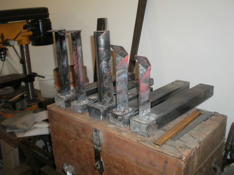
The configuration of the secondary air supply which generated the best results was found through a lot of experiments. Twelve different combinations were tested, variables such as horizontal and vertical tube sizes along with the shapes and lengths of the air outlets were investigated. The next photograph shows five of those combinations. All of those are affected by corrosion, some more than others. The model which will be in use in this particular heater is the second from right, the final version used has a slightly shorter vertical tube. The vertical part of the tube in the middle is a round tube and as such similar to Matt Walker's pre-port tube.
The secondary air supply (the floor channel) is fitted in a recess in the firebox floor, in fact the fire is on top of it. See the photo of the completed core if you're unsure about where the floor channel is situated. The primary air inlet (via the flap on the door) as well as feeding the main fire also feeds air into the secondary air channel situated directly behind it. This primary air inlet too is situated low in the door (see photo). As the temperature of the air entering is very much lower than combustion chamber environment it will naturally remain low (cold air falls, in this case 'cold air stays low') and therefore the secondary air tube is fully supplied with air at all times.
The hotter the environment, the more air is streaming into the floor channel. The duct itself is heated up by the fire which in turn pre-heats the incoming air. The triangle shaped opening at the top of the vertical part injects the air at halfway height in the port.
At the front side of the combustion chamber a steel plate is mounted which diverts the rest of the air upwards. Because of this provision the fire burns a bit more calmly and the chance to get a hefty CO-spike is reduced. See for this provision the relevant drawing in the "Designs" chapter.
For a temperate sea climate this is a large heater equipped with a surprisingly small combustion chamber. With this design it is not needed to employ "tricks" like crisscross logs or "camp fire style" wood loading (used to lessen smoke and aid burning by incorporating lots of air in normal heaters). Such methods are not only no longer needed, but also lessen the load capacity. Just load the box, fuel laying front to back and it will naturally have enough air, caused by the irregularities of the fuel.
One full load in this 150 mm (6") system size heater would weigh in at about 6 kg (13.2 lbs) bone dry medium sized birch logs. The best results with this loading style and floor channel as drawn will be obtained by a top down burn. When lit at the top of the whole batch as far back as possible, a small kindling fire will eat through the whole pile by itself.
Depending on the fuel size and the chimney draw the burn will last between 55 and 90 minutes. The chimney temperature, measured in the centre of the chimney pipe won't get higher than 80 ºCelsius (175 ºF) when the heater is started cold. When the heater is fired a couple of days in succession the highest temperature in the stove pipe will be around 120 ºCelsius (248 ºF). In that last case it is recommended to use larger diameter fuel because the chimney draw will be quite a lot stronger.
All molds and castings, excluding the castings of the core, are made to order by Bergkachel v.o.f. in The Hague, Netherlands. The 3D drawing in SketchUp 2016 format of the complete design is downloadable through this link.
Drawing updated 10/05/2016.
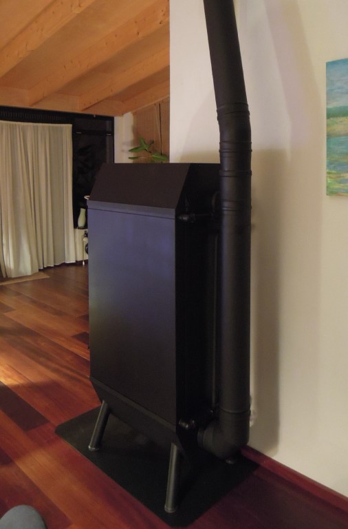
Batchrocket central heating boiler
The design outlined here is made and built by Rémy Bakker, living in the north of Limburg, Netherlands. He lives in the vicinity of the Reichswald in Germany, his nickname is "Holtere", which is an old expression for "woodlot". The whole history of his heater(s) are described in a thread on the Ecologieforum titled "Update bouw houtkachel". It's in Dutch only but lots of pictures are included.
Note: the following is for illustrative purposes only, a system as complex as this should only be undertaken by those competent to do so.
"Our heater is not centrally located in the house and we need quite a lot of heat for the in-floor heating of the rest of the house outside of the living room. In fact, the living room is thoroughly insulated and is a recently built annex to the 1920-ish house. A warm water appliance could be incorporated so this is how the choice for a central heating boiler was made. Connected to a couple of large solar water heater collectors and a similar sized storage of 1000 liter (35 cu ft). The pump starts running when the water temperature in the exchangers is over 75 ºCelsius (167 ºF)."
Some figures:
RBB wood heater for an unpressurized system.
Dimensions of the heater: W x D x H= 48 x 75 x 157 cm (1.57' x 2.46' x 5.15').
Systemsize of the RBB is 150 cm2 (23.3 sq.in.) or 138 mm (5.43") diameter, chimney connection 150 mm (6") diameter.
Internal size of the firebox: W x H x D= 20 x 30 x 50 cm (7.87" x 11.8"x 19.7").
Maximum load 6 kg (13.2 lbs) beech per cycle of 45 minutes.
Heat release directly to the room estimated 2 to 4 kWh (6820 Btu up to 13600 Btu) maximum.
Externally, the sides get to between 60 and 75 ºCelsius (140 and 167 ºF), the same as the water temperature, the rear wall a bit warmer. The front, together with the door becomes hotter, especially the top half (maximum 180 ºC (356 ºF)). This could be lowered when the inside is insulated.
The heater is able to heat the 1000 liter (35 cu ft) water storage up to 75 ºCelsius (167 ºF). When the return temp rises past 75 degrees, firing should be reduced to prevent boiling noises and for safety reasons. A way to counter this effect is to enlarge the exchangers, more volume means it will take more time to get the water to boiling point.

This could be done by using fewer fire tubes and/or making the exchange panels wider. For example with 11 fire tubes instead of 12 like in this implementation. The sides of the exchangers inside the heater could be insulated. As it is now the water is heated up from two sides, from inside the heater above the firebox and inside the tubes.
Unpressurized systems are more prone to boiling noises as compared to pressurized systems where the boiling temperature can be as high as 125 ºC (257 ºF). The large side panels of this heater are not designed to tolerate more than "normal" pressures, so this system operates at normal atmospheric pressure.
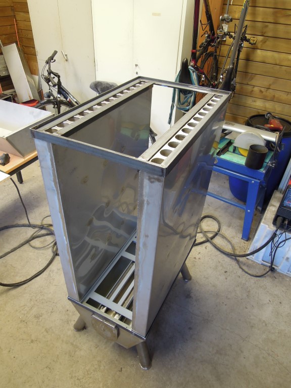
The lower part of the heater is made out of stainless steel because of condensation fluid, which is acidic and could cause corrosion. There's no drain for condensation fluid but this could be done later.
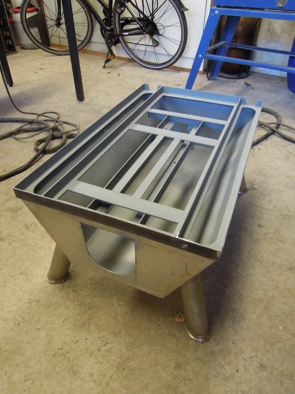
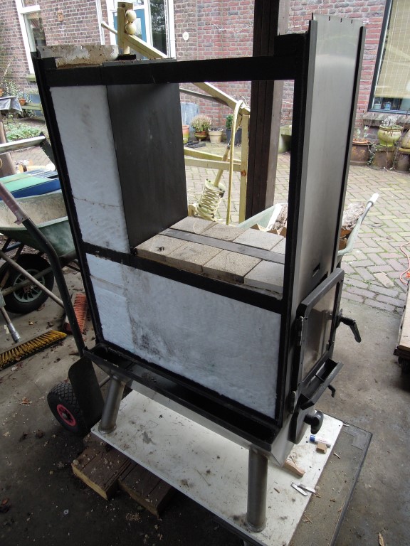
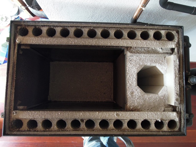
The exhaust gases are coming down through the exchangers on both sides of the ash drawer and stream to the back where the chimney pipe starts. The ash drawer hangs on a couple of rails and is shorter than the depth of the heater. This way, there's always space enough for the gases to stream to the exit hole. In this construction it isn't necessary to make the ash drawer airtight because there's a second p-channel on the slit in the floor of the firebox.
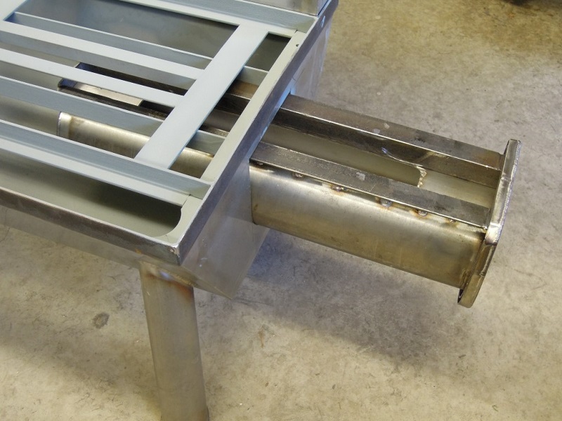
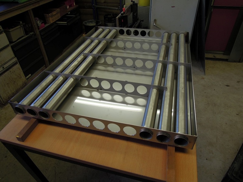
The size of the heat exchangers is 99 x 75 x 7.5 cm (39" x 29.5" x 3"). Each of them contains 12 fire tubes sized 48 mm diameter x 2 mm thickness. At the bottom the tubes are sticking out slightly, to encourage condensation fluid to drip down. The exhaust gases of 900 ºC (1160 ºF) from the rocket core stream down through the fire tubes. The water, contained in the panel around the tubes streams from the bottom up. Internally, there are baffle plates that force the water to take a more circuitous path on its way up through the panel.
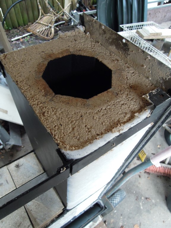
The top of the heater is double skinned with a space of 20 mm (0.79") at the sides and 30 mm (1.18") at the top between the skins. This space is completely filled with superwool to insulate the living space from the very hot inside of the heater.
Pieces of vermiculite board are mounted directly above the riser to protect the steel from overheating. The temperature at the outside of the heater's top is around 50 to 80 ºCelsius (120 to 175 ºF), more or less the same as the sides of the heat exchangers.
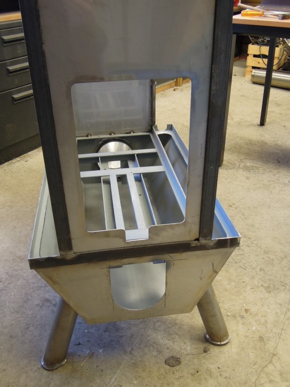
The riser is built of split fire bricks of 30 mm (1 1/4"). All those are cut to an angle of 67.5 degrees on both the longest sides, together they form an octagon riser.
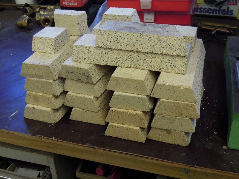
The riser parts are glued together with stove caulk and secured with welding wire. To help maintain strength the joints are staggered, so achieving a running bond.
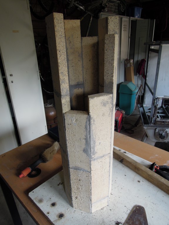
The riser as a whole is secured and insulated with a mix of vermiculite and clay.
The firebox is built out of fire brick boards of 30 x 30 x 4 cm (12" x 12" x 1.57").
The sides of the firebox are also insulated with a layer of superwool. This is done to prevent the firebox from losing too much heat to the exchangers. As always in rocket heaters we lose as little heat as possible from the combustion itself which is an essential part of their efficient operation.
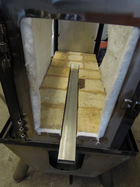
The picture above shows clearly the position of the second P-channel. In a later stage it is clad with vermiculite board, it serves as a lid on the ash drawer as well.
Exhaust gas temperature without turbulators between 80 and 120 ºC (175 to 250 ºF), depending on the water temperature. As can be clearly seen, after the heating season the riser is completely white on the inside and the fly ash on the exchangers is just faintly brownish.
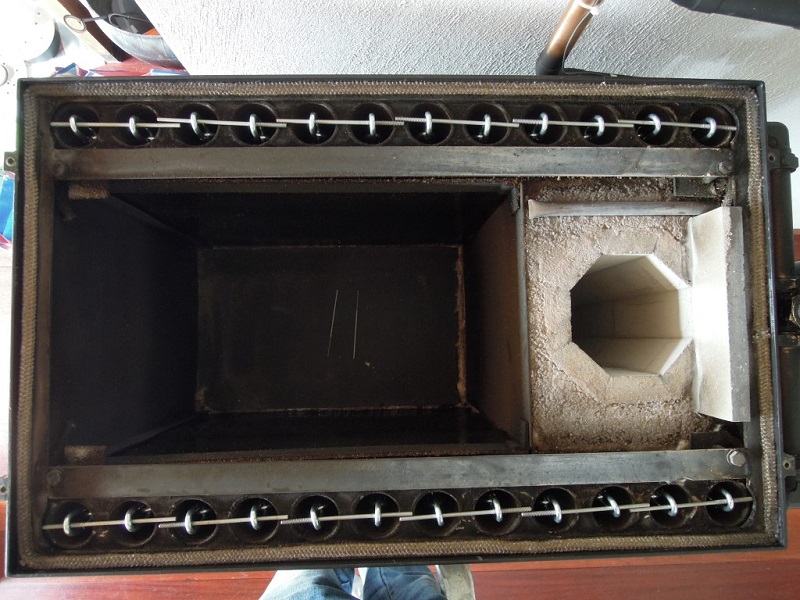
With turbulators (chains with 6 mm (0.25") links) the exhaust is the same as the water temperature, maximum 75 to 80 ºC (167 to 175 ºF) measured in the center of the chimney pipe.
A drawing of the heat exchangers are available through this link.
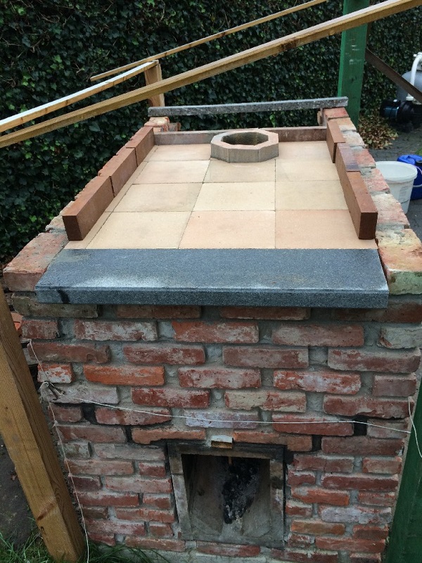
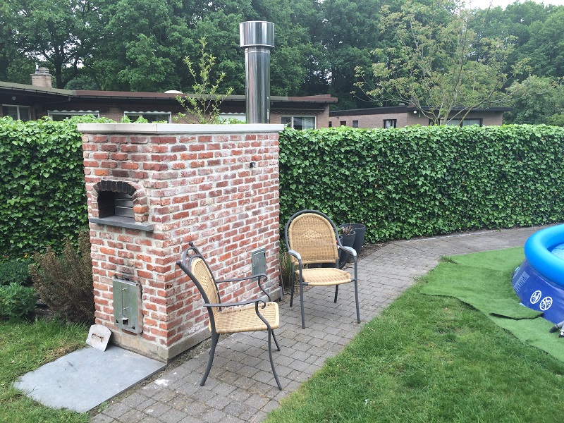
Pizza oven / terrace warmer / pool heater combination
The design outlined here is made and built in 2015 by Tom De Smedt, living in Genk, Belgian Limburg. This article is very much the same as his thread at Donkey32's Rocket Stove Forum and included here with his permission.
Note: a system as complex as this should only be undertaken by those competent to do so.
"After setting up a swimming pool in the garden, and finding out that there isn't much fun in keeping a cold pool tidy that nobody's swimming in, I started playing with the idea to build a wood burning pool heater. Much and most examples on the internet, YouTube DIY versions as well as commercial ones, seemed to be rather smokey contraptions, not to mention dangerous ones, and often plain ugly. Then I stumbled upon the rocket stove technology, and spent quite some time reading up, and thinking about how to use it in an aesthetically pleasing way.
I decided I was going to build a rocket powered pool heater, but given the fact that it would be a time consuming and rather bulky, not to mention costly project, I wanted to have a safety net, in case the pool heater didn't perform as desired. This made me come up with the idea to integrate a pizza oven with a swimming pool heater. When pool performance would be laughable, I could always continue enjoying the pizzaoven part.
In the end, this resulted in the build I would like to show you all in this thread. It's proven to be capable of heating my 16000 liter (565 cu ft) pool from 20 to 30 °C (68 to 86 °F) in 24 hours of wood burning. I did the math, and this would mean that on average, the heater is giving off 10 kW to the pool, which pleases me a great deal. During the building process, it has already served many a pizza, and a few roasted chickens as well.
Given the fact that my wife accepted it, I think it is fairly pleasing to the eye as well, but I will leave that judgement up to you. If anyone would like to attempt the same, I hope they will find inspiration in the following pictures."
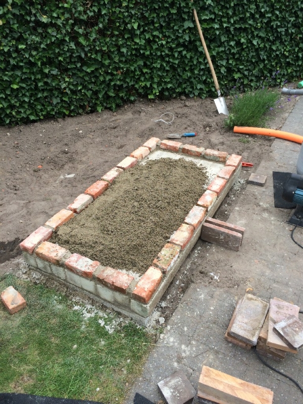
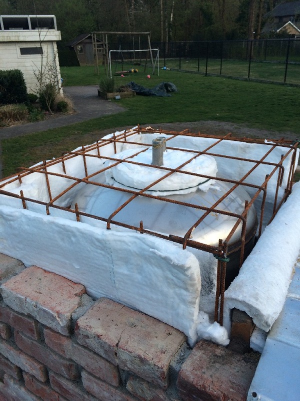
Step one, foundations. Note the pool pump in the background, essentially to the workings of the water heater.

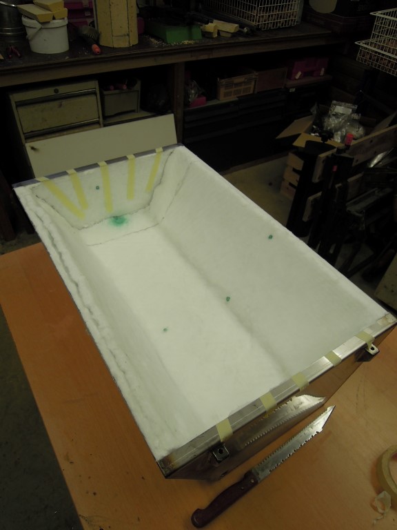
Step two, insulating the base with portland cement / vermiculite mix.
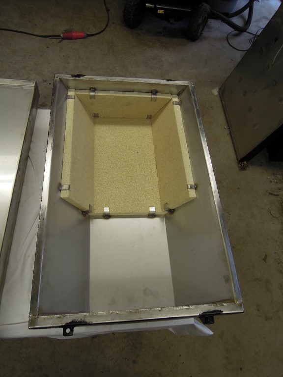
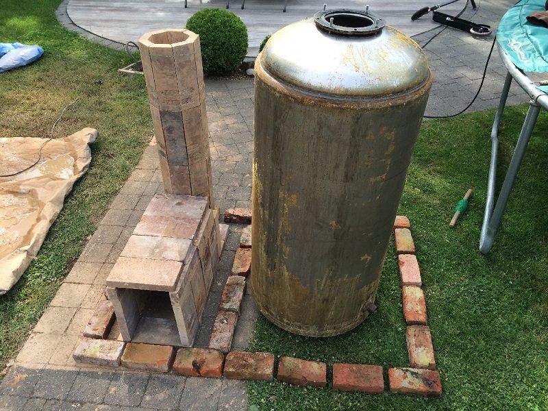
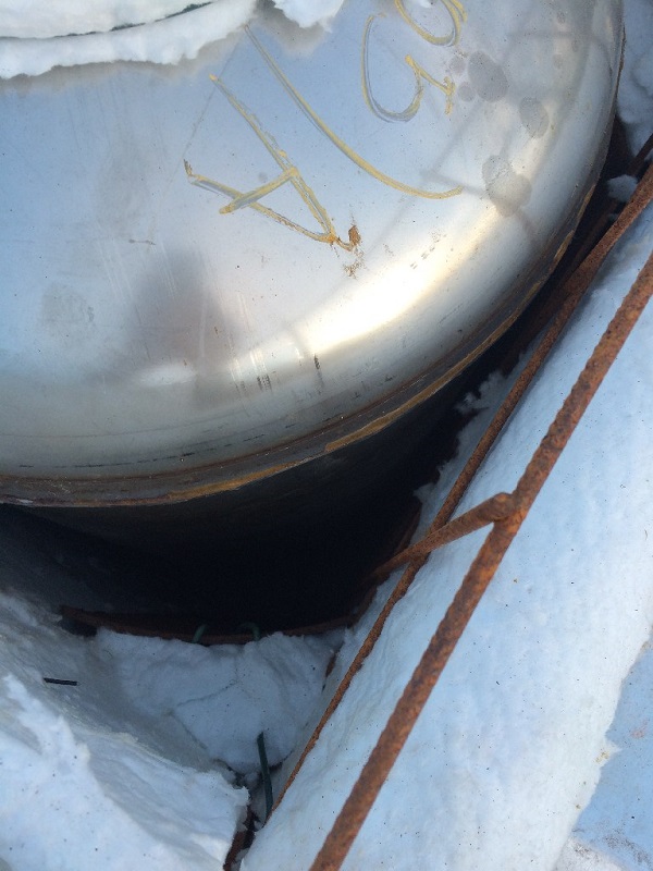
Step three, buying a second hand stainless steel boiler and cutting split fire bricks into parts for a riser and a batch box. Note the final layout happened to be slightly different, in that the boiler is behind the riser.
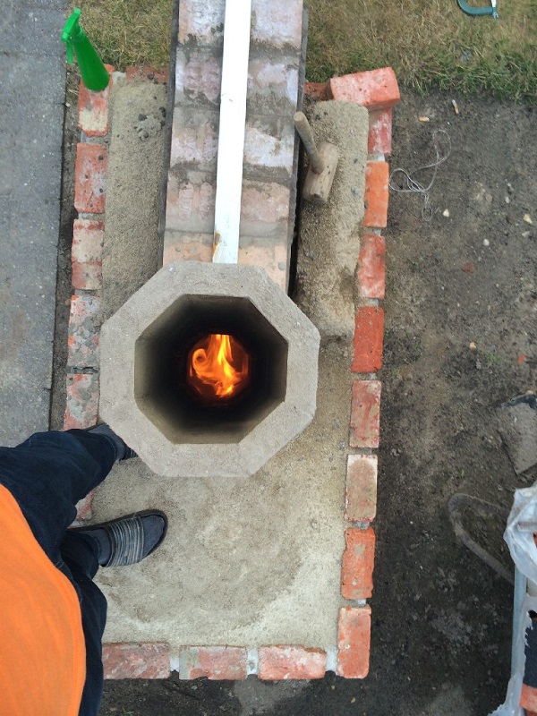
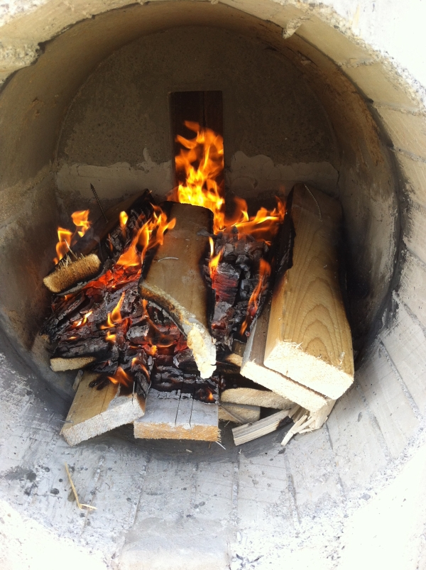
Step four, assembly of the batch box rocket on the foundation, using refractory mortar, and after curing, lighting it. => first success!
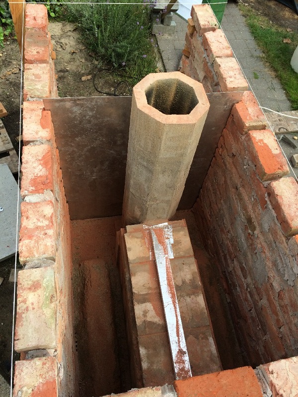
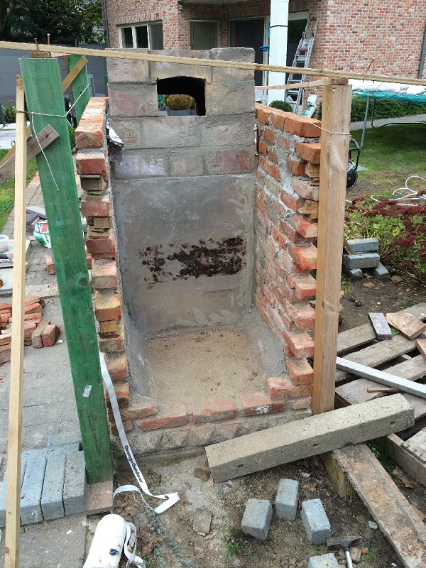
Step five, bricklaying and dividing into two compartments with a stainless steel plate.
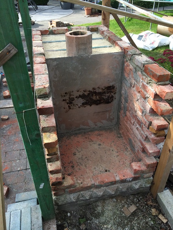
Step six, insulating the rocket stove with vermiculite and creating an oven floor with t-bars and 4 cm thick concrete slabs. T bars were given room for expansion. All in all, maybe not the best technical option, but wanted to keep footprint as small as possible. The black soot on the backplate is from previous firings.
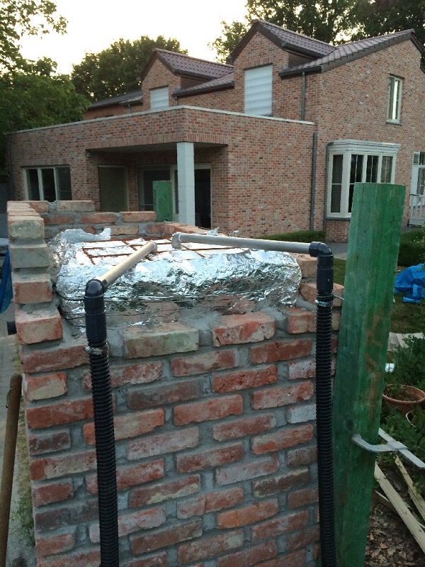
Step seven, insulating the concrete slabs with vermiculite /portland cement mix, and laying refractory tiles. Not much space between the walls and the start of the dome, I know. (small footprint remember) I "insulated" that with 5 layers of aluminum foil, which in the end proved sort of satisfactory. The wall heats up to the point where you can't keep your hand to it for more than a few seconds, but the good thing is that sitting beside the wall in the evening is rather cosy and comfortable.
Step eight, creating a mould for the dome, and building the dome.
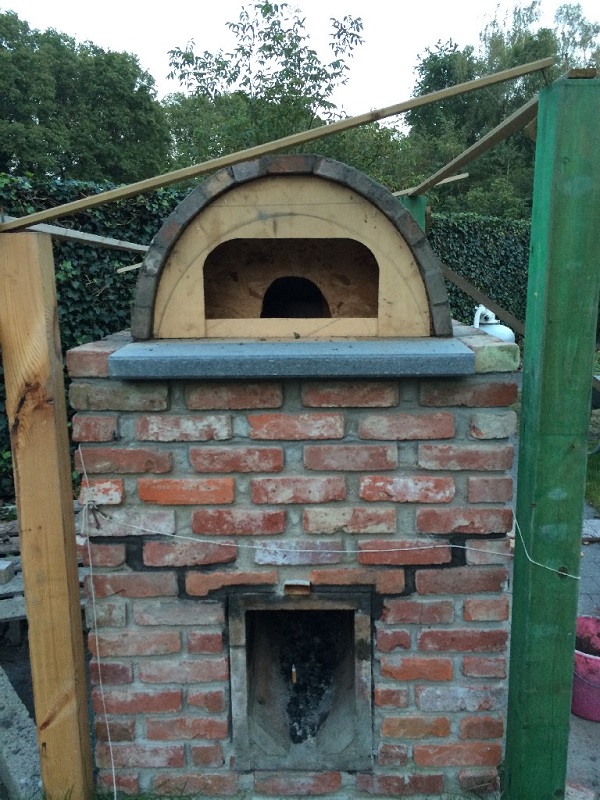
Step nine, taking away the mould, and cutting and installing refractory front and rear walls.
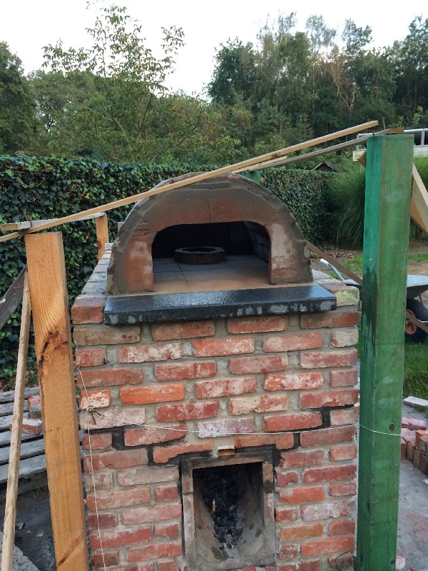
Step ten, bricklaying on a second mould, restarting over and over. Until in the end I had an arch at the front and a closable opening in the back which has the same cross section as the flue, 150 mm diameter. The top of the rear opening is flush with the oven ceiling, to minimize flue gas obstruction.
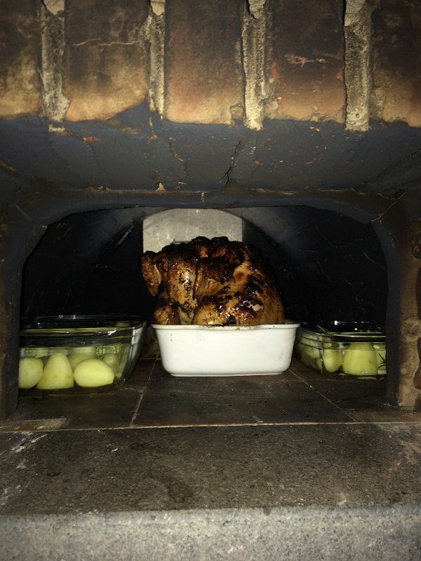
Step eleven, closing the opening with a brick and testing the oven. (beer in the butt chicken)
The oven stood in this stage for quite some time, until I could figure out how I would insulate the walls of the boiler compartment at a reasonable cost, and with good efficiency.
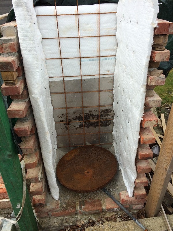
Step twelve, bought a roll of superwool, and created a skeleton I could tie the insulation to and put around the boiler.
I also created a condensation fluid collecting tray from the bottom of the outer shell of the boiler, that I cut off. The outer shell was not stainless steel, so I hesitated to use it for this purpose, but the metalworker who welded the piping to it assured me that I would not see it rust to shreds any time soon. (of course stainless would have been the better option anyway... time will tell)
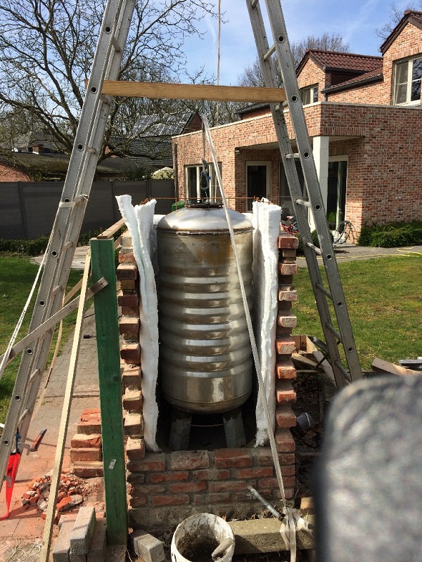
Step thirteen, installing the boiler onto sort of a pedestal, so I would be able to clean out the ashes collecting in the tray.
Step fourteen, filling up the edges of the compartment, to avoid shortcutting of hot flue gas to the exhaust. I used cutouts from the outer shell of the boiler for this, and plugged it at the top with superwool.
(Editor's note: not really necessary, because of the down draft of the gases)
Step fifteen, closing off the top of the boiler, keeping some headspace and insulating it. The longer pipe stub at the top of the boiler is the cold water tube which is reaching down inside close to the bottom, the shorter one is for extracting the hot water close to the top. Between those, there's a thermocoupler probe so the temperature of the water can be monitored. See this small png how this looks like.
Step sixteen, closing up the rear and connecting stainless tubing and PVC pool hoses, surrounding the top with some extra aluminum foil for good measure.
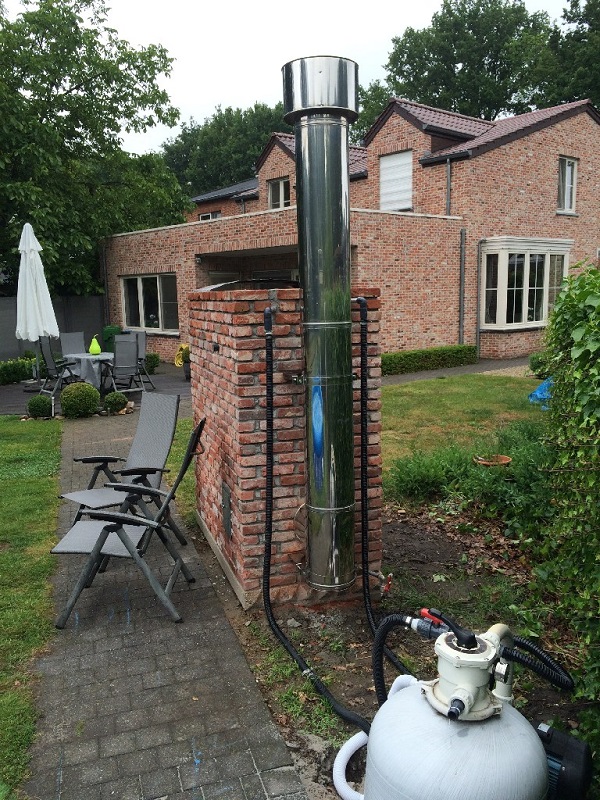
Step seventeen, I covered both the top of the dome and boiler compartment with vermiculite / portland cement mix, to insulate and make it gas tight. Then I bought and installed a second hand insulated stainless steel chimney, and bent some sheet metal and used some leftover insulation to produce two front covers for the oven and the batch box. Stainless steel handles were bought from IKEA.
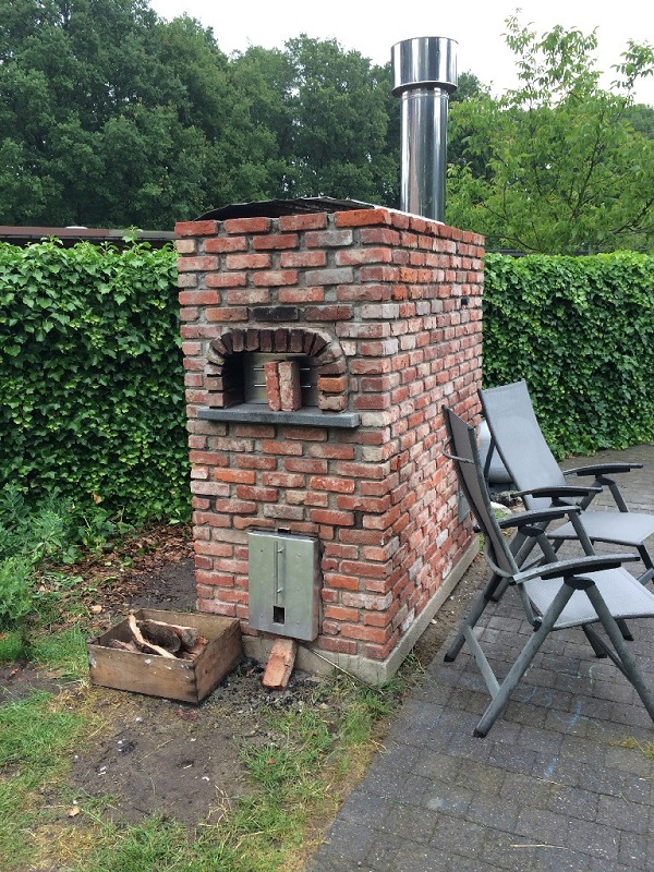
That's where I'm now. I still need to cover the build with a stainless lid, or a bluestone slab, I'm undecided as of yet. I also have some grouting left to do.
(In order to avoid rantings about the dangers of heating water with fire, and possible pressure buildup and so on, I will mention that I consider this design as safe, since the boiler is connected to the pool and pump unit without any valves or obstructions. My pool filter pump is programmed to pump filtered water through the boiler for 15 minutes, every other 15 minutes. In case the power fails, I can always open up the pizza oven door, and close off the back window, to stop heating the water, and avoid melting my hoses with boiling hot water. In the event of failure at least the boiler is outside and not in a dangerous position as it would be in a basement.)
Regarding oven temperature, I have no means of measuring it (yet), but Sunday evening June 25th 2015, the dome and oven floor were absolutely clean, not a speck of soot, or spilled cheese remaining anywhere. I've been led to believe this starts to happen when the walls are between 370 and 400 ºC (698 and 752 ºF).
When I started cooking with the boiler installed, I did notice that the initial heat decreased more quickly than in the past firings, when the back window was closed off. I guess that's not too surprising, plus it's all relatively speaking, the 8th pizza was still ready in under 4 minutes :)
I should mention that, due to the heat, one crack formed in the outside brickwork during one of the first firings. The crack is slightly larger when the oven is hot, and reduces again when the oven is cold. It doesn't seem to get any worse, so I guess it just means it has created its own expansion joint. Better design on my part might have avoided that. If I would redo this, I would not rest the T bars on the outer wall, but on an inner wall, not touching the outer skin.
Step eighteen, the brickwork was grouted around half of July 2015 and I fabricated a sloped, painted hardwood cover for the oven in order to agree more with the theme of the house.
Around the batch rocket the insulation is loose vermiculite, in hindsight it would be better to stabilize this with a little bit of portland cement or clay.
Open systems, without door, p-channel or floor channel
Between July 2017 and June 2018 I designed a number of open systems without a door (and hence) no provision for secondary air. Don't expect those systems to be comparable with closed systems efficiency-wise, the excess air factor is much too large for that. Although there's a strong indication that these heaters are just as clean burning as their higher efficiency brothers.
Please be aware that a heater with no door isn't recommended inside a house. Due to the fact that in essence it is an open fireplace, it could spill smoke inside the living room. Also, no door means the heater can't be closed which could be dangerous while people are asleep. In case the fire isn't completely out, deadly carbon monoxide could spill out of the heater due to weather changes for example.
1: Münster, July 2017
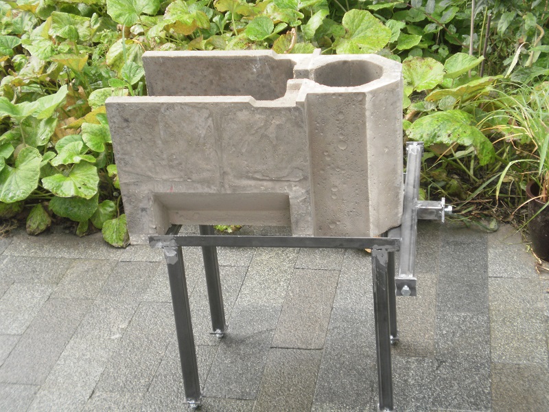
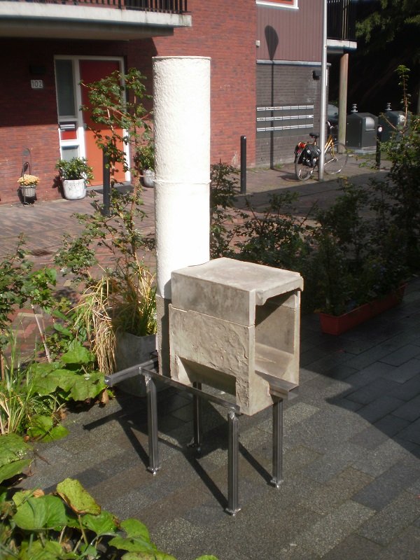
The first open system was mounted inside an art sculpture designed by Oscar Tuazon which was built at the same time during the decennial Sculpture Projecte Münster of 2017. The term ‘open’ has stuck when describing this system. The concrete sculpture was built in the outside air aside a canal and meant as a space for people to hang out. With the possibility to light a fire in the firebox to warm up the concrete column. Which can be very comfortable to lean against during chilly evenings.
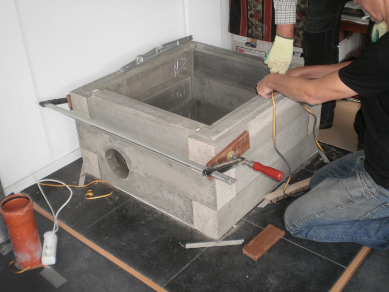
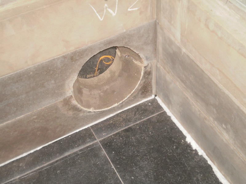
The firebox was a 250 mm system cast as a cylinder to match the hole in the concrete column and set horizontally behind the opening, the riser was cast with an octagonal cross section. The circular firebox' front opening had exactly the same cross section area as the rectangular front opening of a 250 mm system according to the recommended proportions. The riser in the picture appears to be very short, another piece of equal length was placed on top.
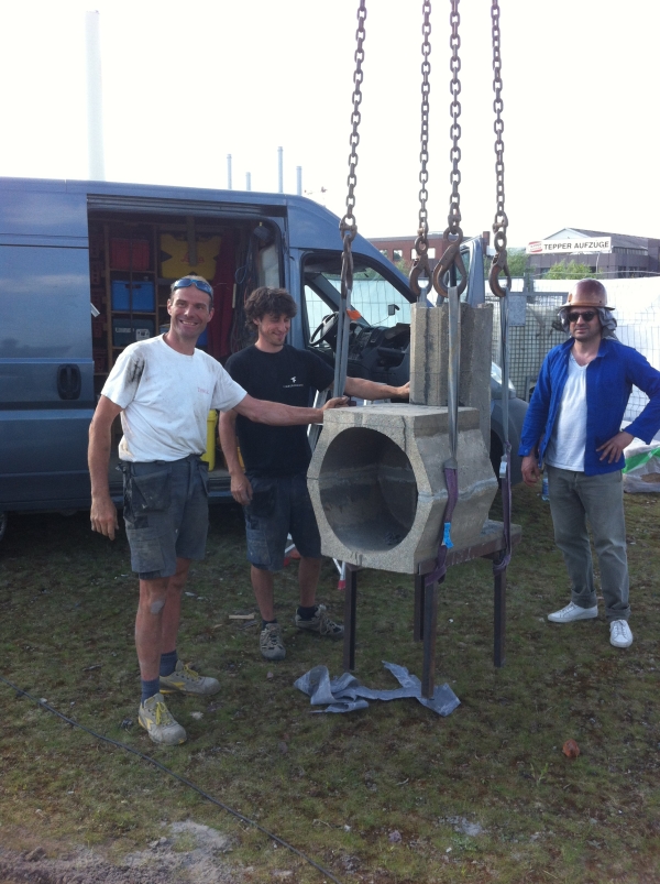
The concrete cylinder being hollow with a closed top served as a single bell of hefty weight, 6 metric tons. The chimney was mounted inside, starting 40 cm above floor level and protruding just 30 cm out of the bell’s top (not visible in the picture). The riser had the normal back sweep (the ramp at the bottom rear of the riser).
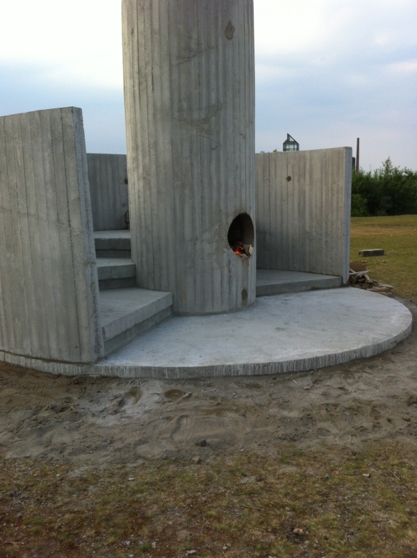
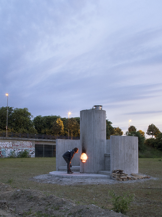
picture © Henning Rogge
2: Free University, Brussels
The second open system was built in the courtyard of the Free University of Brussels (ULB) during April 2018, done as a workshop for and by the students. It was a brick 200 mm system set inside one large brick bell. In outside air again, an inner courtyard on top of a parking garage. What makes this build interesting is that the back wall of the bell was actually an existing wall of a neighbouring building.
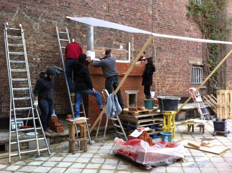
To prevent excessive loss of heat into the large wall, the back wall of the bell is insulated with 25 mm of Superwool. Building the structure according to the recommended values means that the bell is very spacious, even much more spacious than expected. The riser layout was done like the Mallorca build, square, out of split fire bricks, no back sweep, only the chamfered corners at the rear of the riser up to a level as high as the port. Please read about the consequences of a square riser as opposed to a round one in the "Building" chapter.
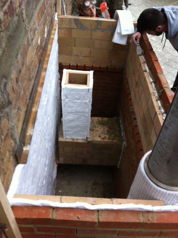
The results, although not tested with a gas analiser, were very encouraging. It worked without too much persuasion just one hour after completing the build. In fact two ladies were still doing pointing work while it was getting dark and the heater was fired up. A lot of water vapour came out the short chimney and after an hour this disappeared completely. The drawing in Sketchup 8 format can be obtained here:
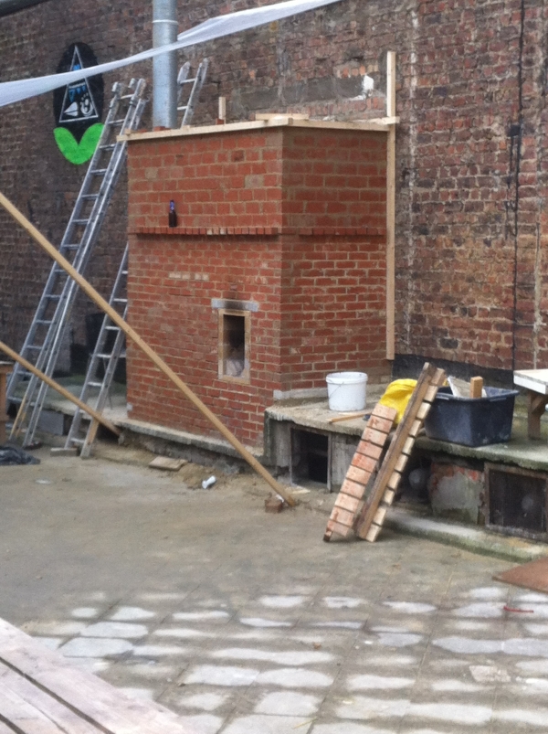
The next morning a video was taken, sadly without the impressive low rumbling sound that gives these heaters the name of Rocket Heaters.
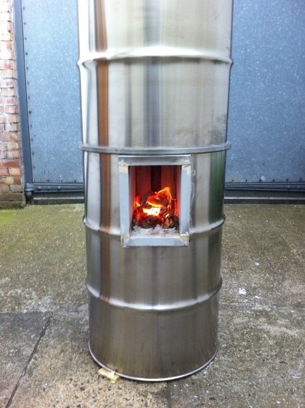
3: Maureen Paley, London
Another one was done in the art gallery of Maureen Paley in London in June of 2018. It consisted of two stainless steel barrels on top of each other and a combustion core built out of insulative refractory board.
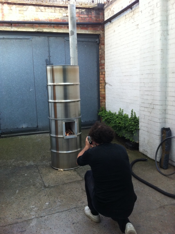
This heater is a system size of 120 mm, so the riser is a square with 120 mm sides (with the remaining values taken from the tables for a size of 120mm). It's built inside a partially open courtyard as an addition to the opening of the art exhibition called Fire! by Oscar Tuazon.
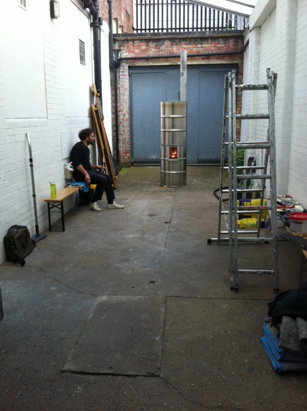
The flue is simply a straight pipe inside the barrels, starting about 20 cm above floor level. It performed very well although at the time it could only be run with small pieces of fuel. No further testing has been done on this one.
All three of the above projects were initiated by Antoine Rocca, docent of architecture at the Free University of Brussels (ULB).
Materials
Concerning materials, there's quite a choice. Firebrick, refractory castable, clay - combined with each other or secondary materials.
(read more)
Metal
When thinking about a wood stove, people tend to picture a box stove of whatever shape. But metal isn't a good material for a Batchrocket, for the combustion core at least. The environment in there is agressive enough for rapid decay.
(read more)
Dimensions and scalability
The most frequently tested version is the one with a riser diameter of 150 mm (6"). But a range of other sizes are perfectly possible.
(read more)
Sizing a batchrocket
How to determine the required system size for a given space.
(read more)
Building a brick core
Being a specialist isn't required in order to build this core unit. With some technical insight, and materials which are relatively easy to come by in most places, a good result is entirely possible.
(read more)
Casting a core
Possible using refractory castable, a material which consists of aluminum cement and among others ground firebrick as the aggregate. Molds need to be build and the material need to be mixed using as little water as possible. Also, a vibrating table is required to condense it in order to get the air out.
(read more)
Bell theory
The word "bell" will be mentioned in the "Applications" chapter quite often. This article explains what it is, how it works and what it is being used for.
(read more)
Bell sizing
How large a bell can be relative to the combustion core is quite important, as is scaling up or down.
(read more)
Materials
In order to build this combustion unit a lot of combinations are possible. For instance, using fire bricks, whether or not mortared with real fire cement or a mix of clay and sand. The thinner split fire bricks or plates held together by a steel frame is another possibility. Casting in a mold of refractory castable (fire concrete) offers other benefits (and also other problems, unfortunately).
Some people used a mix of clay and sand with a little bit of portland cement added in order to obtain a firm core before the thing is fired. When the cement gives up eventually because of the temperature the clay should be reasonably strong by then. A couple of those cores are built entrely out of clay with short natural fibres mixed through for strength. And last but not least: insulating fire bricks, those are ideal from the combustion point of view. Very little mass to heat up and very insulating but have a vulnerability to abrasion as a disadvantage.
Non-insulating constructions (remember, mass doesn't insulate!) should be insulated from the outside. This insulation could be anything as long as it is heat resistant. Expanded perlite or exfoliated vermiculite are fine, especially the somewhat coarse kind mixed with a little bit of clay and some water to prevent sagging. But also ceramic blanket like Superwool is an excellent material for this purpose. Somewhat less known but surely fitting for this purpose are expanded and fired clay granules normally used for hydroculture like Leca.
All these structures could piece by piece lead to an appliance which works really nice and yields spectacular results. Of course a plethora of choices and combinations are possible so there're a lot to choose from.
Metal
Concerning metal in constructive parts: this will lead inevitably to disappointment, it doesn't matter whether it is steel or stainless steel. In an environment sporting temperatures higher than 760 ºC (1400 ºF) combined with substantial excess oxygen and carbon frugality every normal available kind of steel will corrode at a racing pace. After every burn flakes and slices will fall off and in a foreseeable span of time a hole will emerge at the hottest spot. This process is known as spalling, the flakes are dull grey, light weight and almost non-magnetic.
One of the ways to avoid this is keeping the temperature low by leaving out insulation around the hottest spots but that compromises the complete combustion. Another way to let the steel survive is to shield it from air, no oxygen no corrosion. But that is asking for expensive fire resistent coatings or a very small air supply so there isn't enough oxygen left to react with the steel. This last possibility is hard to achieve because by starving the fire of oxygen the quality of the burn is compromised which will result in incomplete combustion once again. However, for some parts the use of steel could be feasible, I'll come back to that when it's appropriate.
Dimensions and scalability
The bulk of development has been done in 2012. The experimental model was one with a 150 mm (6") riser diameter or equivalent. Even back then people asked me for smaller or larger versions of this thing. Jim from Blacksburg, Virginia wanted to build a smaller one, no more than 100 mm (4") riser diameter. Measurements of the 150 mm system were available and with this in hand Jim worked out a scaling method. He found out the common factor which serves as a kind of base figure, all other sizes are a multiple or part of this base figure.
Up until mid-2016 the smallest working model is Jim's, the largest is built by Radek Stastny from Czech Republic and Alex Harpin from Canada, 220 mm (8.66") examples. As of October 2016, the largest system I am aware of is a 250 mm (10") item, built by Pablo Kulbaba (Pablo OresKu) and Ramiro Walti during a workshop in Las Amalias San Pedro in Argentina. The larger ones are somewhat more consistent in performance compared to the smaller brothers but results are good along the entire line. The base figure found by Jim is 72.34% of the riser diameter.
The riser can have a shape that is not the 'perfect round or octagonal' cross section, contrary to long held belief. It can, for example, be square, tried and tested in combination with a floor channel only. Having a square shape is much cheaper and easier to build so this discovery is of great benefit and interest to all Rocket Heater builders. The natural action of the exhaust gas (particularly with the half-octagonal shape of the riser where the gas enters through the port giving the initial swirl) is to assume a circular column shape as it rises. When using a square riser, it must be made larger than a round riser in terms of cross section area, and it must be large enough that the circular exhaust column can fit inside the square without obstruction. Essentially the corners of the square become 'dead space' that do not contribute to, or detract from, the formation or perpetuation of the circular swirl of the exhaust gas. So when sizing the square it means that what was the diameter of the circle becomes the internal dimension of the square. A rectangle is still not considered to be a good shape. As it does not add any benefit in terms of cost or ease of construction over a square it should be ignored.
Both in the Netherlands by Ritsaert Snijder as in the USA by Doug Ptacek spreadsheets are made whereby only the system diameter need to be known and the rest of the dimensions rolls out. The spreadsheet is available here. Tables are also available, there's no need for a computer at the muddy building site, a print on a piece of paper is sufficient. Below is Doug's table, both in inches and in millimeters.
Keep in mind that the riser should be the same diameter as the chimney size. Larger chimneys will work, smaller ones won't.
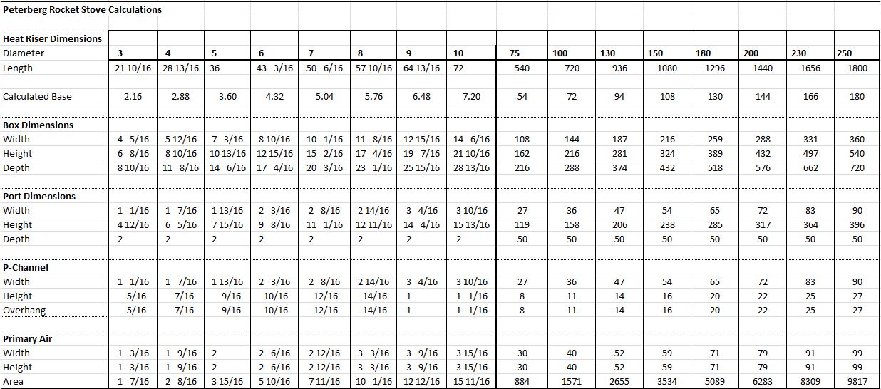
The batchrocket dimensions can also be calculated by hand, because the formula is very simple.
There is a common base number to which all the other dimensions are related. That base number is derived from the diameter (fictional or not) of the riser as explained above.
Base dimension is 72.34% of riser diameter.
Width of firebox is 2 times base.
Height of firebox is 3 times base.
Depth of firebox is 4 to 5.5 times base.
Height of port is 2.2 times base.
Width of port is 0.5 times base.
Height of the riser is 8 to 10 times base, measured from the firebox floor. The firebox floor does consist of a narrow flat surface the width of the port. Left and right there are 45 degree slopes in order to concentrate the glowing charcoal in the middle. Those 45 degree chamfer is part of the dimensions of the firebox. In addition, there’s also a similar shaped piece at the rear bottom of the riser.
The total air inlet is 25% of riser cross section area.
P-channel is 5% riser csa.
Main inlet plus an optional window wash is 20%. Main inlet could be larger when starting cold and is situated level with the floor of the firebox.
P-channel should be as wide as the port or slightly more, for the calculation of the 5% you should take the width of the port, not the actual width of the duct. This duct is hanging over the top of the port the same distance as the depth of the duct.
The back of the p-channel which is resting against the firebox rear wall has been cut away over the height of the overhang.
How to size a batchrocket
Yasin Gach, the translator of the French version, provided a spreadsheet for to calculate the system size of a batchrocket for a given space. It's indicative, not absolute, but it'll give a good idea of the necessary size. The following article is Yasin's, the spreadsheet is available here.
The first step is to calculate the power of each batchrocket, as a function of its internal diameter (i.e. heat riser diameter). By default, the power of a heater is defined as the mean power it delivers on a 24h period with two fires a day. This power is calculated by considering an overall efficiency of 80%. With this efficiency, the combustion of a kilogram of air-dried wood will deliver 3.7 kWh of energy.
The bigger the internal diameter, the heavier the load of wood for each fire:
Internal diameter (mm) -- Wood load (kg) -- Mean power considering two fires a day (kW)
- 125 mm — 3.5 kg — 1.1 kW
- 140 mm — 4.9 kg — 1.5 kW
- 150 mm — 6.0 kg — 1.9 kW
- 175 mm — 9.5 kg — 2.9 kW
- 200 mm — 14.2 kg — 4.4 kW
- 230 mm — 21.6 kg — 6.7 kW
- 250 mm — 27.8 kg — 8.6 kW
The second step is to calculate the heat losses of the house (or the room) to be heated, which depends on three factors: the volume of the house, the insulation, and the required difference of temperature between the exterior and the interior.
So the formula is Q = G*V*DT with Q being the heat losses (W), G being the insulation factor, V the volume of the house (m3), and DT the required difference of temperature between the exterior and the interior (°C). G is estimated in comparison to a set of classical values:
- 1.8 for an old, leaky, stone and clay mortar house (classical french farmhouses)
- 1.6 for a house in bricks, stones or breeze blocks without insulation
- 1.4 for a house insulated with 4 cm of polystyrene
- 1.2 for a house insulated with 10 cm of polystyrene
- 0.8 for a recent house with 37 cm thick insulating clay bricks for example
- 0.5 for a strawbale house for example
The third step is the actual calculation. The idea is to calculate the heat losses of the house and then to choose a size of batchrocket whose power is superior to the heat losses. The following is an example of the calculation for a given circumstance. This is only to show how the spreadsheet works, in practice download the spreadsheet and fill in the yellow fields as applicable for your own circumstance, the spreadsheet does the rest using the method that follows.
For example, let's take a 60 m2 stone and clay mortar house with a 2.5 m ceiling height. The volume of the house is then 150 m3. There is 20 cm of rockwool insulation under the roof. The joints have been done recently and the joinery is quite airtight. We can then take a coefficient G=1.6. During the winter the temperature floats around 0°C and can occasionaly drop to -5°C for a few days. The heat losses that need to be overcome in order to maintain a temperature of 20°C inside the house during these cold periods is Q = 1.6*60*2.5*25 = 6 kW. The chosen batchrocket size is then a 230 mm system which is able to generate a power of 6.7 kW.
Of course it is a very simple approximation of the heating requirements of a house, but the advantage of mass heaters is that it is not a problem to oversize them. With cast iron stoves, it becomes much more of a problem because if you oversize your heater, then you will have to make slow, dirty fires in order not to overheat your house. With mass heaters the fire always stays hot and clean, you just have to light it less often.
I have had consistently workable results using this method on 5 batchrockets heaters I built last year (2016) that are in daily operation now. The very important point is to always oversize the heater. Of course, it is possible to fire a mass heater that isn't powerful enough three or more times a day, but this will lower the overall efficiency because the mass needs time to deliver the accumulated heat.
Artur Milicki, translator of the Polish language version, pointed out that in regions of the world that are much cooler than France (e.g. Poland, Russia, Scandinavia, Canada, etc.), where the minimum temperatures in the heating season may occasionally drop to -20 ° C or lower, oversizing the mass heater as encouraged by Yasin may become impractical and sometimes even impossible.
Since the heating capacity of mass heaters, which heat up with the heat accumulated in their walls, also depends on the intensity and frequency of firing, it can be increased by up to 50%. Therefore, when preparing the design of the stove, we can set the heating capacity of the mass heater at the level of 65-75% of the maximum hourly heat losses in heated rooms. We then assume that during the biggest frosts, which happen only occasionally (few or several days in a heating season), we will be able to cover the maximum demand for heat by longer or more frequent firing.
Building a brick core
The setup with fire bricks seems obvious because in the building materials trade this product is readily available. There's a disadvantage, the bricks need to be worked with a wet saw or a suitable grinder with cutting wheel. To illustrate what something like a brick core looks like here's a picture below.
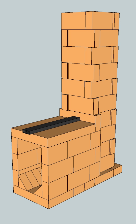
This is a complete core, system (riser diameter) size 150 mm (6") built of fire bricks. There are a couple of ways of closing the top of the firebox. The drawing shows a fire brick plate, there are traders in most countries who sell these. A top plate out of refractory castable is also a possibility, when a mold is simple to make and a vibrating table is already at hand. Another way to do it is laying bricks in a cantilever arrange, since they are too short to cover the distance in one span.
In order to try this construction outside in the open air normal red bricks can be used and a concrete sidewalk paver as top plate. Don't expect it to survive for long but it gives an indication what is actually happening inside. A sizeable mirror held at an angle of 45 degrees above the riser will allow spectators to view down and see what is happening in there. Be careful though, at full tilt this core is capable of spitting out a temperature of 700 ºC (1470 ºF) quite easily.
Dry stacking of the bricks won't work, too much air is drawn in through all the small holes and crevices. Complete combustion won't happen because of this. In order to seal it clay and sand could be used or even mud slurry between the bricks would be adequate. Also thin set for tile work from Home Depot or something like that would work. Another material suitable to try things out is air entrained concrete, sold under a plethora of names all over the world. This is light, insulative and cheap, easy to cut with a normal hand saw and sports limited heat resistancy.
All versions of the p-channel (the black steel tube which runs over the firebox and ends directly over the port) are best lit by means of a small kindling fire directly in front, but definitely not in, the port. When that fire is burning well the rest of the batch quantity can be loaded. Load the fuel only lengthwise, front to back with few spaces between pieces. Leave at least 50 mm (2") free between the fuel and the ceiling of the firebox. Take care there's no fuel, however small, sticking in the port itself. When it is, this will result in a badly smoking device, garanteed.
Casting a core
This can be done using refractory concrete, also refractory castable, consisting of aluminum cement and among others ground fire brick as aggregate. Molds need to be made, the castable need to be mixed with as little water as possible and a vibrating table is best to drive the air out. It can be done without that table but the end quality won't be as good.
The molds can be made out of sheet material such as coated plywood and screwed together. The internal shapes and cavities can be formed by using extruded polystyrene foam or any suitable material that can be shaped by you, MDF, builders bog, wood. Working this materials can be done with a good table saw machine. Details are easily done with coarse sandpaper, especially when using the foam. The pieces can be glued inside the mold and onto each other using double sided tape, the type which is made to glue carpeting to the floor. Most of the time releasing the cast piece out of the mold means the shaping material need to cut/chiseled out of the cast.
Below is an example of a mold which is made like that. The pictured mold wasn't ready yet, this is only to show what it looks like.
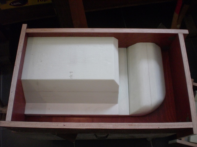
The disadvantage of a mold like this means it's a one-time affair, a one-off mold. Using this a couple of times or more isn't easily done unless the shape is very simple with large release angles. In order to do production runs it would be better to build a positive, called "mothermold" or "plug" out of woody material and cast a negative production mold out of polyurethane rubber. It's a professional opportunity and suited to commercial endeavours because the process and materials are quite expensive.
Applying a release agent in the mold prior to casting is necessary to aid release, because refractory concrete adheres very strongly to almost every surface, even steel. A lot of materials could serve as this agent, beeswax is good. Normally I use a mineral oil like two stroke oil or gearbox oil. Don't forget to wipe off excess oil with a rag, a very thin film is sufficient. Another mean to this end could be an aerosol canister of WD40 provided it's applied sparingly.
Use as litlle water as possible to mix through the concrete, much less water is needed for curing as compared to enough plasticity in order to become a workable material. A concrete mixer isn't actually suitable because for free fall to work lots more water is needed. Too little water in a concrete mixer leads to balling, inside every ball there will be material which isn't humidified. When the amount of concrete isn't too large the mixing can be done by hand, personally I have done this no other way than with a trowel and a mortar shell. The best solution is a paddle mixer but for one time use this is a very expensive solution.
In order to condense the concrete sufficiently by getting the air out, a range of techniques are available. Shaking, prodding, a mini poker vibrator, an impact drill with a bolt in, you name it. For a good quality refractory product done in a mold a vibrating table is actually indispensable. Such a table is an inelaborate utensil as opposed to a paddle mixer. Personally, many years ago I used waste crate timber to assemble one, a fat induction motor equipped with a bolt and an eccentric strip on the axle fixed under the top plate and two back springs of a moped cutted in half between frame and top plate.
But... it can be done much more simply. With a car tyre, a plate of plywood and an old drilling machine. Here is a video which shows how it is assembled.
In this video a real vibrating motor is used but a power drill fixed under the plate equipped with a simple eccentric would work as well. Even nicer: a small hand sander mounted under the top plate works perfectly. When possible, use a machine which is capable of variable speed. When an oil-like fluid is appearing on the surface of the refractory, stop vibrating. This is a sure sign of separation of the components which will result in a poor quality product when vibration is commenced.
As soon as everything is properly condensed place the mold on a flat and level surface. The product will become inevitably thicker on one side when the mold is off level. During curing the refractory will get hot, most of the water on the surface will evaporate whereby the cast side will become powdery. It would be best to cover the fresh cast with plastic sheeting to keep the water in. Most of the refractory castables can be released after 8 hours at room temperature. Ninety percent of maximum strength is achieved by that time, the rest will follow in about a week, sometimes two. In practise, the cast is kept in the mold overnight. Of course there's no objection to a longer stay in the mold.
To cast a core as a monolith without cracking when the core heats up is virtually impossible. This is caused by expansion of the material when heated. During a burn the temperature isn't equally distributed which is causing cracks. Where the cracks appear aren't the hottest spots but the coldest instead. The hotter parts start to expand and the cooler parts are staying behind and tearing apart. The solution is to be found in dividing the whole thing in such a way that the hotter and cooler parts are separated. The seams can be sealed with aluminum silicate paper and the parts held together by means of steel wire, a large hose clamp or a steel support frame.
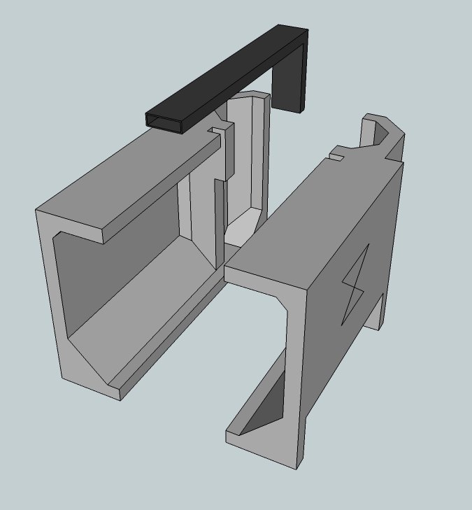
It is very sensible to keep the wall thickness small and where applicable to stick fill pieces in the mold. The mass will be as low as possible this way, less mass to warm up will mean the thing is quicker up to working temperature.
The Bell, how it works and why
An important term that needs to be understood is "Bell". It has become part of the language of building these types of heaters and as such its usage and meaning must be understood. Contrary to what might be expected, it has nothing to do with a church bell or any other bell of that nature. It is nothing more than a large enclosed space, meaning 'four walls, a top and bottom'. It can be any shape that works best for the situation, it can be constructed of any material that suits the purpose best, including steel/metal, brick, refractory, stone, clay dug out of the backyard mixed with straw.
You can build for speed, you can build it for looks,
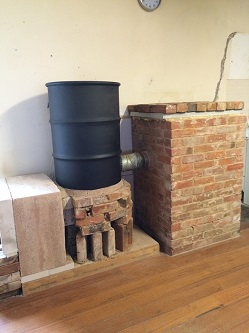
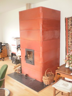
you can build it for cheapness and each purpose has a range of materials that suit that purpose.
When we put these two elements together, the combustion units described earlier coupled with a bell, we have made ourselves a bell heater. As you will see from some of the sketchup drawings we combine these two elements so that the very hot, very clean exhaust from the combustion unit enters the bell and 'allows the magic to happen'. The combustion unit can be external or internal to the bell.
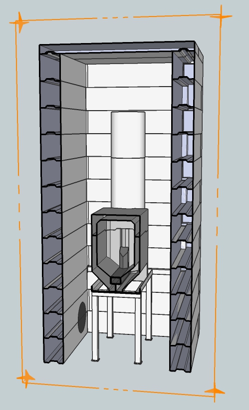
So, having described what a bell is, it is simple to see how and why it works as well as it does. Hot exhaust gas from the combustion unit enters into the bell, and as we all know, hot air rises. As the bell is *very much larger* than the pipe feeding it with the hot exhaust, the hot exhaust does not rush through it as might be first assumed. As it enters the very much larger space of the bell it slows down immensely further allowing the principle of 'hot air rises' to take place. The hottest part of the gases rise to the top of the bell, and gives the heat it contains to the interior surface of the bell and in the process cooling, thus falling within the bell.
As hot exhaust is continually entering the bell, an exit must be provided (in other words, the 'normal chimney flue'). This exit is usually placed as low in the bell as practical. The converse of 'hot air rises' is naturally, 'cold air falls'. It is clear then that the gases which do leave the bell and out the chimney are the coldest gases. In this manner we can easily, and successfully, 'harvest the heat'. The advantages of this is not hard to imagine, all anyone needs to do is recall any normal wood burning space heater and remember how hot the flue gets. In fact, it might not be wrong to say in a conventional wood heater it is the hottest gases that escape, clearly not as good a solution as is being presented here.
A picture tells a thousand words, what a bell is and how it works can be clearly seen below.
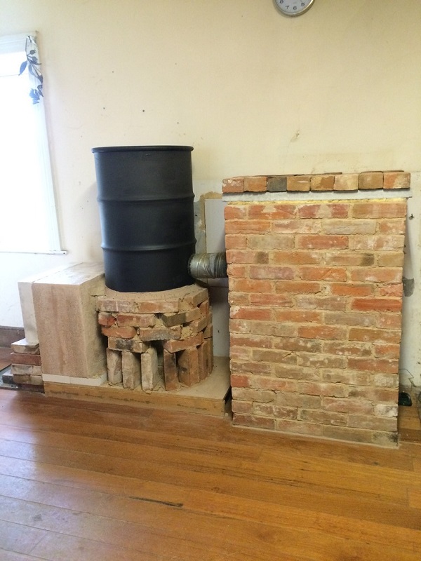
The entry of the hot exhaust from the metal oil drum (at left) can be seen to enter the single skin bell about halfway up. Looking closely at the bottom right, we can see where the temperature measuring probe enters the bell and into the exhaust flue. The inside of the bell is nothing but 'space'. It does allow the hot exhaust to enter, slow down greatly, rise to the top of the bell and give its heat to the bell, cool and then fall down to almost the floor before leaving the bell via the chimney flue. (The use of metal oil drums will be explained in an upcoming section, for now simply grasp the bell concept and how it works.)
The behaviour and the consequences of hot gases rising was first described in 1910 by V. E. Grum-Grzhimailo, professor of metallurgy at the university of Saint Petersburg.
Of course the simple description just above of how a bell harvests the heat does not reflect the true, more complex reality of what occurs. The simple description above was quite a static picture, the reality is that it is a constantly changing very dynamic system indeed. The internal walls of the bell do not 'only' trap the heat, the external walls of the bell radiate heat. At times the internal walls of the bell might get hot enough that they cannot absorb any more heat, and heat absorption will increase/be forced lower down the walls. As the heat carrying capacity of the bell is reached, the temperature of the escaping gases will rise (as they can no longer give heat to the walls). So, a constantly changing set of forces/actions occurring, yet even so the exhaust gas will almost never reach the same temperature as the incoming gas.
If the temperature of the exhaust gas is high enough, and the heat lost to the external world is wanted, then we can extend this idea of the bell by recognising that the exhaust of one bell can be considered as the heat input to another bell. This second bell works in exactly the same way as described above, the end result being that it's exhaust is lower than the temperature of the gases that entered it. This second bell concept is naturally more efficient (usually, ultimately it depends on what the flue temp is... if it is low enough with a single bell then the second is not needed as one bell has done the job). Adding a second bell could increase the efficiency of heat harvesting, but it also introduces greater complexity.
There are rules of thumb to come later that allow us to know the size of the bell that relates to the size of the combustion unit. At all times there must be a certain temperature in the exit flue (roughly 80 - 100 ºC / 175 - 210 ºF) in order for sufficient draw to occur. In other words, we cannot have cooler than ambient air as the flue temp.
An additional real advantage of the bell system is that it creates almost no, or negligible, friction or resistance to the flow of gases through it. That this is achieved with such a simple construction is an added bonus. By comparison, the German/Austrian way of building a mass/masonry heater uses a system of channels to give the heat to the mass. The surface area of these 'long' channels, coupled with the (relatively) small diameter of the channels themselves imposes much greater friction/resistance to the flow of gases. This then requires as a necessity that it be a very strong drafting system indeed in order to overcome the friction. In addition to all of that, we can see that ALL of the gases flow through all of the system together, the hottest together with the coldest as the separation of hot and cold (as in the bell) has not occurred.
The 'simple' bell system, as pictured above, is very effective but has a singular disadvantage, all the mass is located within the single brick skin. This makes them 'large'. There are techniques available that can counteract that. Placing the combustion unit higher within the structure as opposed to floor level results in the storage of heat at a higher temperature because the gases need to sink lower than where the combustion unit is located. Additionally, internal structures (eg, columns) can be built inside the simple brick skin that can absorb, and then release later, heat. With such measures it is possible to reduce the size of bell needed using the simple 'single skin' method.
Almost all of the heaters to be described later are working bell systems in one way or another.
One last comment on the system pictured above. It is an example of what might be called a hybrid, half way between a bell and a metal drum system. It shows the combinations available for the demands required. In the above, the metal bell gives off radiant heat whilst it charges the bell as it exits the house. This brick bell has a four hour lag, by that is meant the exterior surface of the bell reaches its hottest temperature four hours after the fire has reached its hottest temperature. It had to be absorbed and travel from the internal surface of the bricks to the external surface before it can radiate to the room. Instant heat from the metal oil drum, stored heat that is released slowly over night (or indeed until the next burn) from the attached bell. As a matter of interest, the exit temperature of the flue gases (measured in the centre of the gas stream) stays within a range between 50 - 80 ºCelsius (120 -176º Fahrenheit). No doubt some cups of coffee are hotter than that.
Bell sizing
The size of a bell and it's method of calculation needs some clarification. Most people would suppose the heat extraction capacity of the bell is governed by volume, but this is not the case. Broadly speaking the governing factor is surface area, namely the walls and ceiling of the bell, so this is what is used in our sizing of the bell. The shape of the bell is almost insignificant, care only needs to be taken that the gases slow down enough and that undue friction is not created. In practice, the CSA of the bell should be at least 5 times the CSA of the entry flue. The gap between the top of the riser and the top of the bell should measure at least 30 cm (1'). In the vast majority of cases this will be sufficient, though more is better as the more the gases are slowed down the better the separation of hot and cold gases.
The correct sizing of the bell was hard won by experimentation, and like all open source projects contributions came from many different people. Klemen Urbanija from Radomlje, Slovenia found out after a lot of tinkering that a 15 cm (6") system with a single bell with an internal surface area of 6 m² (64.6 sq ft), excluding the floor, gave an exhaust temperature 60 ºCelsius (140 ºFahrenheit). He built his experiment outside the house and changed it several times until the results were satisfying, then he tore it down and moved it inside the house. A new round of problems emerged due to the chimney stack being made of bricks, which extracted heat from the exhaust thereby killing the draw. This needed more tinkering and rebuilding of the bell in order to raise the exhaust temperature and restore the draw. The final result was a figure of 5.3 m² (57 sq ft) of 'heat absorption area'. This is important to grasp, and once grasped it can be seen that the floor area of the bell will not be part of the 'heat absorption area' as the flue exits above it. Equally, if the firebox is built into the bell then the surface area of the firebox within the bell won't play a role in calculating this area as no heat is absorbed there.
The term we use for the total area available for heat absorption within the bell is ISA, short for Internal Surface Area. As noted, this does not include the floor area as that floor does not (directly) absorb heat. The difference between a steel bell which is shedding its heat immediately and one that is storing heat in a mass of stone or brick is marginal in terms of ISA. My workshop heater (see article Three barrel batch rocket) is built out of three oil barrels which together are very close to the same ISA as Klemen's masonry bell and bench. Both systems have a comparable exhaust temperature.
Scaling up of these numbers posed a long-standing problem which was finally solved in 2015. It turned out that the same critical dimension used to scale the size of fireboxes up or down, the cross sectional area of the heat riser, can also be used to scale the bell ISA up and down from the base result determined by Klemen. 2015 was the year that the bell with two cul-de-sac benches was built during the MHA meeting (see article Bell with dead-end benches). The maximum ISA of that 20 cm (8") system and a masonry bell without chimney bypass turned out to be 9.4 m² (101 sq ft). The ratio of Klemen's heat riser CSA to the MHA riser CSA was 1 : 1.77, and the same ratio of 1 : 1.77 appeared in both ISAs. We had found it!
As a consequence we can use the following 'table', and simply extrapolate or interpolate as required. As far as we know, this method works within reasonable limits in both directions.
Riser diameter / Internal Surface area
- 12.5 cm (5") ISA 3.7 m² (39.8 sq ft)
- 15.0 cm (6") ISA 5.3 m² (57 sq ft)
- 17.5 cm (7") ISA 7.2 m² (77.5 sq ft)
- 20.0 cm (8") ISA 9.4 m² (101 sq ft)
- 22.5 cm (9") ISA 11.4 m² (123 sq ft)
- 25.0 cm (10") ISA 14.7 m² (158 sq ft)
When the bell is fitted with a chimney bypass it could be larger than the figures mentioned here but it will make the construction more complicated, not to mention vulnerable to malfunction.
Benen Huntley from Adelaide, South Australia found a simple rule of thumb for to calculate the maximum ISA of the bell for any given system size. Calculate the cross section area of the riser in square meters and multiply that by 300. This will give you the recommended maximum size of the Internal Surface Area (ISA) of a single bell.
For example: a 150 mm system will give you 0.0176715 sq m. Multiplied by 300 will result in 5.3014376 sq m, which rounded off to 5.3 sq m is exactly the recommended maximum value for such a system. Of course taking into account a 150 mm round riser is as good as a square riser with sides of 150 mm, aerodynamically speaking. The round riser is smooth, no corners. The square is larger but has corners and a larger circumference which pose friction to the gases. So in case of a square riser the cross section area of a round riser should be used for this.
Another example: a 200 mm system will give you a cross section area of 0.031415927 m². Again multiplied by 300 comes down to 9.424778 m², rounded off to 9.4 m² is exactly according to the recommended values.
What is a wood fire?
During the combustion of wood the organic molecules are decomposing into smaller pieces. Eventually those become gases, known as woodgas, and are the source of flames as they burn. The results of complete combustion are: heat, carbon dioxide (CO2) and water.
(read more)
Mixing
Woodgas is extremely combustible, explosive even, when it's hot enough and thoroughly mixed with fresh air. This mixing doesn't occur spontaneously, it is achieved because of the highly turbulent conditions generated by the batch box design in the port and riser.
(read more)
Mixing and turbulence in the Batch Box
In the world of Rocket Heater builders the name of that short insulated internal chimney is called a "heat riser". In the Batch Box Rocket the tall and narrow opening at the bottom side of the riser is called the "port". The combination of riser and combustion chamber is called the "core". The way turbulence is invoked is significally different from a normal wood stove.
(read more)
Heat
Another evironmental factor is just as important as fuel/air mixing: maintaining high temperature during combustion. This shouldn't be taken lightly. During development temperatures as high as 1200 ºCelsius (2190 ºFahrenheit) have been measured in the riser. Higher temperatures result in cleaner combustion... and can also be a challenge for construction materials selected to be used!
(read more)
Cautions
It has been found experimentally that the respective ratios between the sizes of the combustion chamber, the port, the riser and the air intakes for good combustion are quite specific numbers. A relatively small change in dimensions that change the tested ratios could be enough to disrupt the correct functioning of the heater. Also, a proper chimney is very important.
(read more)
Exhaust gas measurements
The measurements that eventually led to the final Batch Box Rocket are done with a digital gas analyzer, the Testo 330-2. This device measures in real time during every "testrun" the temperature of the exhaust gases, the oxygen level (O2) and the content of carbon monoxide (CO). These measurements provided the necessary feedback so we could understand empirically how to improve combustion - not just a guess.
(read more)
Air streams in the port
Since 2012 a lot more is known about what the air flows in the port looks like and what their respective function is.
(read more)
How does wood burn in a fire?
The fire triangle shows the three things needed for a fire to start and keep going.
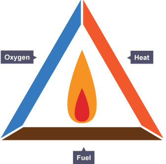
The complete combustion of wood (which is made up of hydrocarbons) results in the following: the hydrogen atoms combine with oxygen to make water vapour (H2O), the carbon atoms combine with oxygen to make carbon dioxide (CO2), and the maximum amount of energy is released.
These same end products are found in natural gas burners.
Lessen or remove one of the sides of the triangle then combustion will not be complete combustion but rather incomplete combustion. Water vapour and carbon dioxide are still produced, but two other products are also produced: carbon monoxide (CO), a colourless toxic gas and particles of carbon, which appear as soot and smoke. Additionally, the maximum amount of heat is NOT produced.
On the surface, burning wood does not seem too difficult, place some small dry branches with paper, put a match to it and the fire is started. Once we have the fire, to have it burn cleanly takes just a bit more thought and effort. We need higher temperatures than the few hundred degrees of a small fire and we need to 'keep it under control', not let it grow excessively. By insulating the combustion chamber and even more important, the heat riser, the heat generated from the fire is kept 'within the fire' maintaining a high combustion temperature wich aids in more complete combustion.
The result of these 'new conditions' (very high heat, 'Goldilocks air supply'-not too much, not too little, juuust right) will be a smokeless fire. Whilst being simple aims, a lot of effort was required to find the parameters presented here that achieve this smokeless fire. To understand why there is no smoke, it must be realised that smoke is simply unburnt fuel, nothing more, nothing less. In fact, up to 60% of the available energy of wood is found in these combustible gases. So smoke is not 'just a nuisance' which affects a large area in the outside environment, it is factually 'money up the chimney' in a very real sense. Money Up In Smoke!
Quite literally, apart from around one percent ash, the entire content of wood can be converted into heat**, and as such smoke is only an indicator of incomplete conversion of fuel into heat. These heaters, as described earlier, have very high temperatures of combustion, so the smoke is very hot in the combustion chamber and in the heat riser. We combine pre-heated air with that smoke which results in spontaneous combustion of the smoke. Even the rightly feared carbon monoxide -a deadly poison- is in fact simply unburnt fuel (recall above that in complete combustion CO is not a product of wood burning). CO has no odour of it's own, so when "town gas" which contained up to 8% CO was used for heat well into the twentieth century mercaptan (a foul smelling substance) was always added to the gas, simply to alert people to any leaks or unlit burners. The point remains though, CO is a fuel (and used as such in town gas) and all of the wood's energy content can be extracted if burnt correctly.
** Whilst this is strictly true, a few points must be understood to put this into a real world context. These heaters will not be used in a laboratory with pure oxygen, they will be used at home with ambient air. Even weather conditions will vary and influence the burn. Most importantly, all air dried wood will contain some moisture. This needs to be driven off before combustion of the wood can take place. To boil off water takes a tremendous amount of energy as shown below.
The graph shows how the temperature of water rises as energy is added. (it starts from below freezing point which we will ignore. Unless the wood you use is itself below freezing!) As energy is added (the horizontal axis), the temperature rises along the straight line C, for every 'bit' of energy added there is a corresponding rise in temperature which is why it is a straight line.
When the water reaches boiling point (100 ºC at sea level) it no longer gets any hotter (seen by line D, it is horizontal even though energy is still being put into the system) During this stage, the energy being absorbed by the water is not making the water any hotter, but rather is making the water change from 'liquid to gas', and this takes place with no change in temperature. Line E will ONLY begin once all of the water has become steam.
Unless we have a condensing boiler, that energy required to turn the water to steam is lost from the system, and into the atmosphere. So, in real world practice, these are some of the losses that do and will occur. The *very*important *point* to be taken from this is, NEVER burn anything other than dry wood. Now you know why.
The following video is a fine example of the flammability of smoke.
Mixing and turbulence
Strangely enough, wood itself does not burn. It is similar to petrol, petrol itself does not burn. If you are quick enough you can douse a match in liquid petrol. It is not recommended that you try it, as most likely the match will ignite the mixture of petrol vapours and oxygen just above the liquid petrol. Once that is understood, it is clear then that it is wood 'vapours' mixed with oxygen that are the substances that burn. Heat causes the chemical components in the wood to break down into smaller, flammable components which then combine with oxygen (in the presence of heat), in turn releasing more heat which causes the cycle to continue. A pure woodgas flame should be blue, hard to see in sunlight. Because there's also glowing carbon dust carried with the flame the colour is red, orange or yellow, the higher the temperature the lighter the colour. When there's a lot of gas in the flame and a tiny bit of carbon it could appear as yellow-purple.
Once it is understood that it is the substances released from the wood by heat that combine with oxygen, we can see that complete and thorough mixing of these substances with oxygen is needed for complete combustion. In practice this is the most important objective to achieve and the most difficult. A column of smoke rising from a fire will most likely burn on its 'outer surface', the interface between the smoke (fuel) and the oxygen rich air. Inside the column of smoke there is very little oxygen hence no combustion. It finally leaves as smoke (unburnt fuel) because even though it eventually meets enough oxygen it has cooled enough that combustion does not occur. Recall that there are three conditions necessary for combustion, fuel, oxygen and heat.
The common method used in combustion heaters to induce this oxygen and fuel mixing is to inject fresh air (usually not pre heated) into the fire from multiple locations. A lot of air is needed for this conventional wood burning system, which is a serious disadvantage because it will lower the temperature of the fire, one of the three conditions needed for complete combustion. In metal stoves this cooling of the fire is not regarded as a disadvantage but rather an advantage, as the temperatures that can be reached from a wood fire are great enough that the steel, even stainless steel, will be destroyed in a surprisingly short time frame. The combination of an oxygen rich and carbon poor environment coupled with high temperatures will corrode the steel very rapidly. As a result, during every burn severe spalling at the metal surface will occur at the hottest spots.
The heaters described here are designed to maintain the hottest burn temperatures possible -far greater than metal heaters can withstand- and ensure proper mixing of the fuel gas and oxygen by methods described in the following section.
Mixing and turbulence in the Batch Box Rocket
The mixing of wood gas and oxygen in the batch box heater is achieved by the carefully designed geometry of the combustion core and the correct positioning of both the primary and secondary air intakes. These critical dimensions will be given later. The arrangement of these building components is quite simple and shown in the 3D cutaway illustration below. The combustion chamber which is longer than it is wide vents to the rear, where a vertical insulated 'chimney' is placed. This is the heat riser referred to above. The function of the combustion chamber is naturally to combust the wood, the function of the insulated heat riser is to allow the final (and complete) combustion of any wood gas produced from the wood fire. From the preceding sections we now understand what is needed to have that complete combustion, fuel (the wood gas), heat (from the fire and from the combustion of wood gas itself. Note again that especially the riser is heavily insulated, ensuring as little heat as possible is lost from any combustion process) and oxygen.
Note particularly the connection between these two elements of combustion chamber and heat riser, a high and narrow opening between the two. This is known as the 'port'. It is actually 70% cross sectional area of the cross section of the heat riser (the cross sectional area of the heat riser is one of the 'standard dimensions' in these heaters, namely a dimension from which other dimensions can be scaled). The port itself is 72.34% of the riser's cross section area, but due to the overhang of the secondary air p-channel this is reduced to 70%. This sudden narrowing in the path of the gas stream has a very important function, as the *same* amount of gas is flowing through the system at all times, when it comes across (or passes through) a narrower opening, it must then speed up at that point (remember, the same amount of gas is passing through at all times and all places). The result of that speeding up at that exact point is that the pressure at that point lowers.
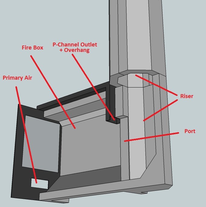
The picture above shows a cut-away view of 1/2 the combustion chamber and the lower heat riser.
Now referring to the diagram, secondary air is delivered through a hollow tube (shown in black at the top of the combustion chamber) connects the external air directly to the point of lowest air pressure in the system, the opening of the port.This form of secondary air intake is known as a P-channel and is one of the early innovations I created that noticeably improves combustion.
This then causes air (or more properly oxygen) to be introduced into the gas stream as it enters the port. As can be imagined, we now have the three conditions needed for combustion, fuel, heat and oxygen. The wood gas is already extremely hot, there is an awful lot of heat in this location, all we need now is the final complete mixing of the oxygen and wood gas. One last point to be noted now, as the secondary air being introduced into the port has to pass through the steel pipe located on top of the fire, it has been pre-heated on it's journey to the port. This pre-heating of incoming air assists in keeping the combustion temperature high.
The thorough and complete mixing of the wood gas and oxygen occurs as the mixture passes through the narrow port and into the heat riser behind. As the gas flow speeds up through the restriction of the port and then slows down abruptly when it reaches the *larger* space behind the port, a massive pile up in the gas flow occurs as the still fast moving molecules passing through the port slam into the suddenly slowed molecules in front of them. This creates considerable turbulence and is continuous as long as the velocity of the gases are higher in the port than in the riser, the large majority of the burn time. These conditions cause the flammable gases to mix into a swirling double vortex in first a horizontal plane and then an ascending double corkscrew as it rises within the heat riser as it exits the system.
The ascending double corkscrew forces the gases to take a much longer path (and hence take longer time) than if they were to go straight up. That this longer travel occurs within a well insulated, extremely hot environment allows the mixed fuel and oxygen to readily combust.
The speeding up of gases as they pass through a restriction is known as "the venturi effect", a law of physics first described by Daniel Bernoulli in the 18th century. The highly chaotic conditions created by this arrangement can be seen in this short video filmed looking down the heat riser and directly at the exit of the port, where the massive pile up occurs and the double vortex/ascending corkscrew is formed.
The rather unique way these heaters create the turbulent conditions required for complete mixing of oxygen and fuel has other favorable results for combustion efficiency. The metal box heaters' blunt sledgehammer approach means lots of air was introduced. This extends the life of these heaters but as noted reduces efficiency. Because the preheated secondary air in the batch box heater is introduced into the best injection point for complete mixing to occur, we do not need anywhere near the same amount of introduced air as metal heaters. So the total cross section area of the combined air intakes is smaller than would be expected in a normal box stove. These smaller than expected air inlets are perhaps even more surprising when it is seen how quickly the fuel is consumed in these heaters.
One last explanation of why 'excess amounts of cool air' is contrary to good efficiency. The essential component in air for combustion is oxygen. Any other component in air is only a passenger, it contributes nothing to the combustion but only serves to cool the fire (they are known as ballast gases. Just as on a ship, ballast is only excess weight and not cargo). As you can see these heaters, by careful use of geometry and taking advantage of natural laws, we introduce the right amount of oxygen to the exact spot required for complete mixing and combustion.
Maybe we can extend this idea of 'goldilocks air'. Not only is it not too much or too little air, juuust right, it is also in juuust the right place.
These heaters generate a typical noise, a low rumbling (but strangely comforting) sound. In fact, it is this characteristic sound found in all of these variants of heaters that gave them the name 'Rocket Stoves'. The short video that follows gives an indication of this characteristic sound, this particular example is in a metal housing so has more of a 'ring' to it, builds that employ masonry or brick housings the timbre changes to a less ringy, lower rumbling sound that is not offensive at all.
Lots of heat
Both the firebox and heat riser are insulated heavily, with particular emphasis on insulation of the heat riser (where the temperatures can be the greatest). This enables the whole to more quickly reach optimum operating temperature and enhances the combustion of the woodgas/oxygen mixture which is of course the basis of heater efficiency.
Important point
It is important to realise that the shapes and dimensions of the combustion unit are quite critical. Variations from these are effectively untested. Your proposed variation may have hit upon a winner, but without testing no-one will ever know). The specific values of 'tightness' of these ratios of design dimensions and ratios is quite logical, they are responsible for what's going on in there.
To achieve the goals of this heater (smoke free highly efficient combustion that can be followed and built by others) it is important that the developed and tested dimensions are followed quite closely.
A proper chimney is required, a chimney is the 'engine' of any wood combustion heater, and is the motive force that creates sufficient draft for clean combustion. As discussed above, the air inlets are smaller than 'expected' and as such are perhaps more easily affected by variations from the design given here. Ratios of the design are to be found in the "Building" section. When the flue temperatures rises (and hence the draft) the air inlet can be decreased, or larger pieces of wood used. Larger more 'chunky' pieces of wood have less surface area than a similar weight of 'finely divided' wood.
These heaters burn the fuel load without the need for restrictions in the air supply or any other measure used to 'slow the burn down for longevity' as done in conventional wood stoves. It should be clear by now that for maximum efficiency and cleanliness of the burn those types of incoming air restriction measures only harm that goal. And so to harness or profitably utilise the heat created we need a large radiating surface or a sufficiently large mass to absorb and slowly release the stored heat. These different approaches will be covered later.
A curious phenomenon of these heaters is the time taken to burn a load. It turns out (rather counter-intuitively) that full load of wood combusts in about the same time as a half load of wood (or other ratio), from lighting to glowing ember phase. So it can be seen that a full load of wood delivers a surprisingly large amount of energy in a given time. Hence we need ways to harvest this heat which will be discussed in the following pages.
Results
In the last four years (2012 thru 2016) I've executed hundreds of runs on the core presented here, and am satisfied a stable dependable combustion heater has been designed. The Testo 330-2 is a gas analyzer which measures the flue output and from that data calculates the efficiency of the burn, and can be connected to a computer as I have done to generate its own line diagram and spreadsheets.
The test shown in the above diagram has been run in a warm heater, as can be deduced by the starting temperature (measured in the flue outlet, in degrees Celsius, represented by the blue line). As mentioned earlier, a 'hot' (already up to working temperature) flue will have a correspondingly strong draw, and so in this run the fire developed quickly. During the run the oxygen level (green line) dropped below what I consider as the border between optimum and non optimum (6% O2). Below that figure runs the chance of higher (purple line) CO outputs (as insufficient oxygen is present). That did not happen in this case as can be seen, so whilst that risk is present it is clear that excellent burns can still be obtained. From all of the earlier discussion given on combustion it can be seen/understood that the oxygen levels, and the flue temperature are directly linked to the efficiency of the burn. The efficiency is shown by the red line.
When the oxygen content does not drop below 10% with a correspondingly low flue temperature of 80 ºC (176 ºF) the efficiency will be higher than shown in the above graph. However lower exhaust gas temperatures means less draft and can have repercussions on combustion because of lower flow velocity through the system.
These graphs that show the inter-relationship between the various parameters of the burn are a graphical way to understand the 'Important Point' made above, that it is doubtful that a departure from the descriptions given here will result in a more optimum heater. Of course it IS possible, but highly unlikely. The interactions within the heater are very complex, and any change has to be evaluated by actual measurement by testing similar to that shown here.
The above graphic is of course a very nice one and for this reason not very representative. A somewhat more normal looking diagram which is generated during development in 2012 could be this one:
Comparing the graphs we can learn a few things (like why the Testo is absolutely essential in knowing exactly what happens during a burn) and see how this burn is more representative than the "cherry picked" stellar example just above. As you can see the extremely low CO levels (pink line) which indicate complete combustion does not occur quite so soon as before, nor does it last as long. Also observe that the Oxygen level (green line) does not go as low, but is still at a very nice level. The oxygen measurement is known as 'excess O2'.
The above is the graphical representation of a very ferocious burn, roaring, joggly and bumpy and occasionally also smoking. Recent developments came to a close with much better results, this will be discussed in the "Core designs" chapter.
Working of the air streams
August, 2020
Since the start of development in 2012, how the batch box rocket works has become much clearer. That the BBR has good scalability (readily enlarged or decreased in size) suggests the presence of underlying fundamental principles.
Eight years later there are some conclusions to be drawn, supported in some respects by people who better understand aerodynamics than ordinary mortals. Those conclusions are based on observations made by multiple builders and developers on different continents. In no case are the following conclusions scientifically substantiated, they are only plausible.
1# The current explanation of why such a hot and fierce fire can be attained is attributed to the pressure difference between the front and rear of the fire chamber.The port acts as a venturi, explained earlier in this chapter. In that venturi the air velocity is greater and the pressure correspondingly lower than at the front where the air enters. That differential pressure is always greater than the draft of the chimney, the port acts as an amplifier. The larger the difference, the brighter the fire, similar perhaps to a fan blown fire. That is also why the time that elapses from ignition to the glowing phase with half a batch under the same conditions is almost the same as with a full batch. That full batch produces a larger fire, a stronger negative pressure in the port and therefore also a faster combustion. It is not the case that a quarter of a load also takes as long, apparently there is a limit. A very hot and clear fire delivers the most complete combustion.
2# When the riser is viewed from above, it is clear that the stream of fire through the port appears to be narrower than the port itself. The speed of that flow is also greater than what can be expected based on what is visible in the firebox. This has to do with the square edges of the port. This point was discussed extensively with Dr. Larry Winiarski * during a workshop in Warsaw, July 2015. Some builders had already chamfered or rounded the edges of the port a number of times, in an attempt to make it more attractive. If that chamfer was large enough, about one-third or more of the port’s depth, it was sufficient to destroy complete combustion in almost all cases. The end result is black smoke from the chimney, just because of the all too smooth curves.
Possible explanation of this phenomenon: sharp right-angle edges cause a lot of small turbulence along the walls of the port. That wall turbulence also slows down the flow along the walls. In the middle of the port the speed remains high, which makes the current seem narrower to the eye. Due to the delay on the left and right, the flow splits easily and the two flows curl, creating the double vortex. The residence time in the hot riser is extended this way which allows more of the wood gas to combust.
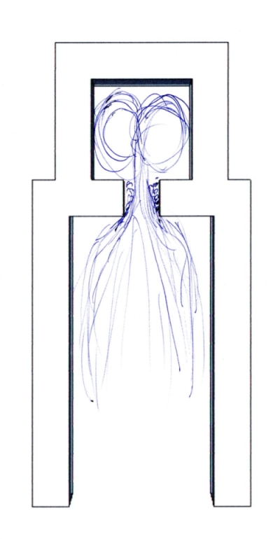
Thus the port should always have two right angles and should open up in the center of the riser.
For example, it is tempting to build a sidewinder in such a way that the back wall of the firebox is flush with the wall of the port. This situation does not meet the conditions outlined above and the properties of the batch rocket may be worse as a result. If the port is not built in the center of the riser but on one side, a single vortex is created. The residence time in the hot environment of the riser then becomes shorter, which in turn affects the quality of combustion.
3# A well-functioning batchrocket shows a horizontal flame, especially at the beginning of the combustion when the afterburning starts. And that flame appears in the bottom half of the port while the top half is completely empty to the eye.
Especially in the early stages of development, some batchrockets were built where the port had the full height of the firebox rear wall. Even though the width was made smaller to compensate, the result was always bad to worse as opposed to using the currently common piece of wall above the port.
In addition, with open systems (see Applications) the phenomenon occurs that combustion without a door and without secondary air supply is still very good. Yield is lower but by not more than 4% or 5%. Also in this variant the flame tend to ignite very low in the riser.
The explanation for all three of the above phenomena probably lies in the flow of air passing over the fire towards the port. Because the air above the fire gets very hot, it flows unimpeded along the ceiling. At the rear wall, the current is bent down and accelerated by the venturi action as soon as it enters the port. The greater the air speed at that moment, the less easily the flow changes direction. Until the stream encounters some obstacle that forces it to go another way, the air through the openings between the pieces of fuel in the firebox together forms such an obstacle. The flames in the firebox are blown to the rear and the flow of air from above forces it down. In a closed system, a p-channel or floor channel provides additional air at exactly that location.
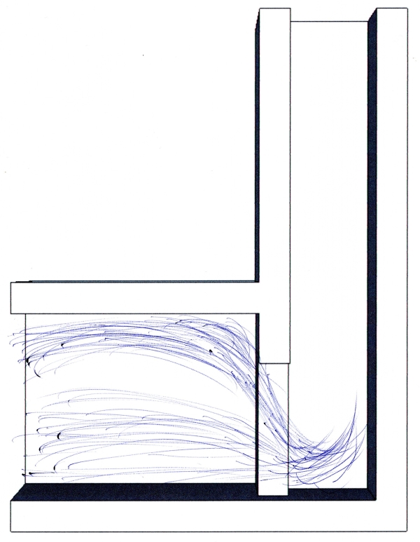
An open system takes advantage of this effect, allowing sufficient fresh and hot air to enter the port and riser in an aggressively turbulent environment. So it is clear that a port the full height of the firebox does not work properly, the hot air from the ceiling simply passes straight into the riser without creating any down-forcing turbulence. And lastly, this may also explain why an object like a piece of wood sticking into the port can destroy the desired complete combustion. The currents are disrupted and the aerodynamics of it all change completely. By withdrawing that piece of wood, the entire system will revert back to proper functioning again within a minute.
Please be aware that a heater with no door isn't recommended inside a house. Due to the fact that in essence it is an open fireplace, it could spill smoke inside the living room. Also, no door means the heater can't be closed which could be dangerous while people are asleep. In case the fire isn't completely out, deadly carbon monoxide could spill out of the heater due to weather changes for example.
*Larry Winiarski is widely regarded as the creator of the original rocket stove. Created as a more efficient alternative to traditional open fires in many developing countries and refugee camps where cooking is done on a wood fire.