
")

")


Materials
Concerning materials, there's quite a choice. Firebrick, refractory castable, clay - combined with each other or secondary materials.
(read more)
Metal
When thinking about a wood stove, people tend to picture a box stove of whatever shape. But metal isn't a good material for a Batchrocket, for the combustion core at least. The environment in there is agressive enough for rapid decay.
(read more)
Dimensions and scalability
The most frequently tested version is the one with a riser diameter of 150 mm (6"). But a range of other sizes are perfectly possible.
(read more)
Sizing a batchrocket
How to determine the required system size for a given space.
(read more)
Building a brick core
Being a specialist isn't required in order to build this core unit. With some technical insight, and materials which are relatively easy to come by in most places, a good result is entirely possible.
(read more)
Casting a core
Possible using refractory castable, a material which consists of aluminum cement and among others ground firebrick as the aggregate. Molds need to be build and the material need to be mixed using as little water as possible. Also, a vibrating table is required to condense it in order to get the air out.
(read more)
Bell theory
The word "bell" will be mentioned in the "Applications" chapter quite often. This article explains what it is, how it works and what it is being used for.
(read more)
Bell sizing
How large a bell can be relative to the combustion core is quite important, as is scaling up or down.
(read more)
Materials
In order to build this combustion unit a lot of combinations are possible. For instance, using fire bricks, whether or not mortared with real fire cement or a mix of clay and sand. The thinner split fire bricks or plates held together by a steel frame is another possibility. Casting in a mold of refractory castable (fire concrete) offers other benefits (and also other problems, unfortunately).
Some people used a mix of clay and sand with a little bit of portland cement added in order to obtain a firm core before the thing is fired. When the cement gives up eventually because of the temperature the clay should be reasonably strong by then. A couple of those cores are built entrely out of clay with short natural fibres mixed through for strength. And last but not least: insulating fire bricks, those are ideal from the combustion point of view. Very little mass to heat up and very insulating but have a vulnerability to abrasion as a disadvantage.
Non-insulating constructions (remember, mass doesn't insulate!) should be insulated from the outside. This insulation could be anything as long as it is heat resistant. Expanded perlite or exfoliated vermiculite are fine, especially the somewhat coarse kind mixed with a little bit of clay and some water to prevent sagging. But also ceramic blanket like Superwool is an excellent material for this purpose. Somewhat less known but surely fitting for this purpose are expanded and fired clay granules normally used for hydroculture like Leca.
All these structures could piece by piece lead to an appliance which works really nice and yields spectacular results. Of course a plethora of choices and combinations are possible so there're a lot to choose from.
Metal
Concerning metal in constructive parts: this will lead inevitably to disappointment, it doesn't matter whether it is steel or stainless steel. In an environment sporting temperatures higher than 760 ºC (1400 ºF) combined with substantial excess oxygen and carbon frugality every normal available kind of steel will corrode at a racing pace. After every burn flakes and slices will fall off and in a foreseeable span of time a hole will emerge at the hottest spot. This process is known as spalling, the flakes are dull grey, light weight and almost non-magnetic.
One of the ways to avoid this is keeping the temperature low by leaving out insulation around the hottest spots but that compromises the complete combustion. Another way to let the steel survive is to shield it from air, no oxygen no corrosion. But that is asking for expensive fire resistent coatings or a very small air supply so there isn't enough oxygen left to react with the steel. This last possibility is hard to achieve because by starving the fire of oxygen the quality of the burn is compromised which will result in incomplete combustion once again. However, for some parts the use of steel could be feasible, I'll come back to that when it's appropriate.
Dimensions and scalability
The bulk of development has been done in 2012. The experimental model was one with a 150 mm (6") riser diameter or equivalent. Even back then people asked me for smaller or larger versions of this thing. Jim from Blacksburg, Virginia wanted to build a smaller one, no more than 100 mm (4") riser diameter. Measurements of the 150 mm system were available and with this in hand Jim worked out a scaling method. He found out the common factor which serves as a kind of base figure, all other sizes are a multiple or part of this base figure.
Up until mid-2016 the smallest working model is Jim's, the largest is built by Radek Stastny from Czech Republic and Alex Harpin from Canada, 220 mm (8.66") examples. As of October 2016, the largest system I am aware of is a 250 mm (10") item, built by Pablo Kulbaba (Pablo OresKu) and Ramiro Walti during a workshop in Las Amalias San Pedro in Argentina. The larger ones are somewhat more consistent in performance compared to the smaller brothers but results are good along the entire line. The base figure found by Jim is 72.34% of the riser diameter.
The riser can have a shape that is not the 'perfect round or octagonal' cross section, contrary to long held belief. It can, for example, be square, tried and tested in combination with a floor channel only. Having a square shape is much cheaper and easier to build so this discovery is of great benefit and interest to all Rocket Heater builders. The natural action of the exhaust gas (particularly with the half-octagonal shape of the riser where the gas enters through the port giving the initial swirl) is to assume a circular column shape as it rises. When using a square riser, it must be made larger than a round riser in terms of cross section area, and it must be large enough that the circular exhaust column can fit inside the square without obstruction. Essentially the corners of the square become 'dead space' that do not contribute to, or detract from, the formation or perpetuation of the circular swirl of the exhaust gas. So when sizing the square it means that what was the diameter of the circle becomes the internal dimension of the square. A rectangle is still not considered to be a good shape. As it does not add any benefit in terms of cost or ease of construction over a square it should be ignored.
Both in the Netherlands by Ritsaert Snijder as in the USA by Doug Ptacek spreadsheets are made whereby only the system diameter need to be known and the rest of the dimensions rolls out. The spreadsheet is available here. Tables are also available, there's no need for a computer at the muddy building site, a print on a piece of paper is sufficient. Below is Doug's table, both in inches and in millimeters.
Keep in mind that the riser should be the same diameter as the chimney size. Larger chimneys will work, smaller ones won't.
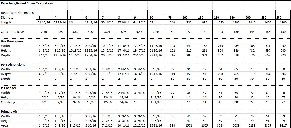
The batchrocket dimensions can also be calculated by hand, because the formula is very simple.
There is a common base number to which all the other dimensions are related. That base number is derived from the diameter (fictional or not) of the riser as explained above.
Base dimension is 72.34% of riser diameter.
Width of firebox is 2 times base.
Height of firebox is 3 times base.
Depth of firebox is 4 to 5.5 times base.
Height of port is 2.2 times base.
Width of port is 0.5 times base.
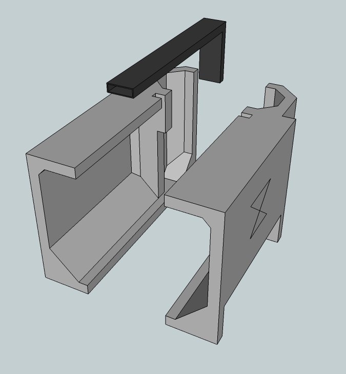
Height of the riser is 8 to 10 times base, measured from the firebox floor. The firebox floor does consist of a narrow flat surface the width of the port. Left and right there are 45 degree slopes in order to concentrate the glowing charcoal in the middle. Those 45 degree chamfer is part of the dimensions of the firebox. In addition, there’s also a similar shaped piece at the rear bottom of the riser.
The total air inlet is 25% of riser cross section area.
P-channel is 5% riser csa.
Main inlet plus an optional window wash is 20%. Main inlet could be larger when starting cold and is situated level with the floor of the firebox.
P-channel should be as wide as the port or slightly more, for the calculation of the 5% you should take the width of the port, not the actual width of the duct. This duct is hanging over the top of the port the same distance as the depth of the duct.
The back of the p-channel which is resting against the firebox rear wall has been cut away over the height of the overhang.
How to size a batchrocket
Yasin Gach, the translator of the French version, provided a spreadsheet for to calculate the system size of a batchrocket for a given space. It's indicative, not absolute, but it'll give a good idea of the necessary size. The following article is Yasin's, the spreadsheet is available here.
The first step is to calculate the power of each batchrocket, as a function of its internal diameter (i.e. heat riser diameter). By default, the power of a heater is defined as the mean power it delivers on a 24h period with two fires a day. This power is calculated by considering an overall efficiency of 80%. With this efficiency, the combustion of a kilogram of air-dried wood will deliver 3.7 kWh of energy.
The bigger the internal diameter, the heavier the load of wood for each fire:
Internal diameter (mm) -- Wood load (kg) -- Mean power considering two fires a day (kW)
- 125 mm — 3.5 kg — 1.1 kW
- 140 mm — 4.9 kg — 1.5 kW
- 150 mm — 6.0 kg — 1.9 kW
- 175 mm — 9.5 kg — 2.9 kW
- 200 mm — 14.2 kg — 4.4 kW
- 230 mm — 21.6 kg — 6.7 kW
- 250 mm — 27.8 kg — 8.6 kW
The second step is to calculate the heat losses of the house (or the room) to be heated, which depends on three factors: the volume of the house, the insulation, and the required difference of temperature between the exterior and the interior.
So the formula is Q = G*V*DT with Q being the heat losses (W), G being the insulation factor, V the volume of the house (m3), and DT the required difference of temperature between the exterior and the interior (°C). G is estimated in comparison to a set of classical values:
- 1.8 for an old, leaky, stone and clay mortar house (classical french farmhouses)
- 1.6 for a house in bricks, stones or breeze blocks without insulation
- 1.4 for a house insulated with 4 cm of polystyrene
- 1.2 for a house insulated with 10 cm of polystyrene
- 0.8 for a recent house with 37 cm thick insulating clay bricks for example
- 0.5 for a strawbale house for example
The third step is the actual calculation. The idea is to calculate the heat losses of the house and then to choose a size of batchrocket whose power is superior to the heat losses. The following is an example of the calculation for a given circumstance. This is only to show how the spreadsheet works, in practice download the spreadsheet and fill in the yellow fields as applicable for your own circumstance, the spreadsheet does the rest using the method that follows.
For example, let's take a 60 m2 stone and clay mortar house with a 2.5 m ceiling height. The volume of the house is then 150 m3. There is 20 cm of rockwool insulation under the roof. The joints have been done recently and the joinery is quite airtight. We can then take a coefficient G=1.6. During the winter the temperature floats around 0°C and can occasionaly drop to -5°C for a few days. The heat losses that need to be overcome in order to maintain a temperature of 20°C inside the house during these cold periods is Q = 1.6*60*2.5*25 = 6 kW. The chosen batchrocket size is then a 230 mm system which is able to generate a power of 6.7 kW.
Of course it is a very simple approximation of the heating requirements of a house, but the advantage of mass heaters is that it is not a problem to oversize them. With cast iron stoves, it becomes much more of a problem because if you oversize your heater, then you will have to make slow, dirty fires in order not to overheat your house. With mass heaters the fire always stays hot and clean, you just have to light it less often.
I have had consistently workable results using this method on 5 batchrockets heaters I built last year (2016) that are in daily operation now. The very important point is to always oversize the heater. Of course, it is possible to fire a mass heater that isn't powerful enough three or more times a day, but this will lower the overall efficiency because the mass needs time to deliver the accumulated heat.
Artur Milicki, translator of the Polish language version, pointed out that in regions of the world that are much cooler than France (e.g. Poland, Russia, Scandinavia, Canada, etc.), where the minimum temperatures in the heating season may occasionally drop to -20 ° C or lower, oversizing the mass heater as encouraged by Yasin may become impractical and sometimes even impossible.
Since the heating capacity of mass heaters, which heat up with the heat accumulated in their walls, also depends on the intensity and frequency of firing, it can be increased by up to 50%. Therefore, when preparing the design of the stove, we can set the heating capacity of the mass heater at the level of 65-75% of the maximum hourly heat losses in heated rooms. We then assume that during the biggest frosts, which happen only occasionally (few or several days in a heating season), we will be able to cover the maximum demand for heat by longer or more frequent firing.
Building a brick core
The setup with fire bricks seems obvious because in the building materials trade this product is readily available. There's a disadvantage, the bricks need to be worked with a wet saw or a suitable grinder with cutting wheel. To illustrate what something like a brick core looks like here's a picture below.
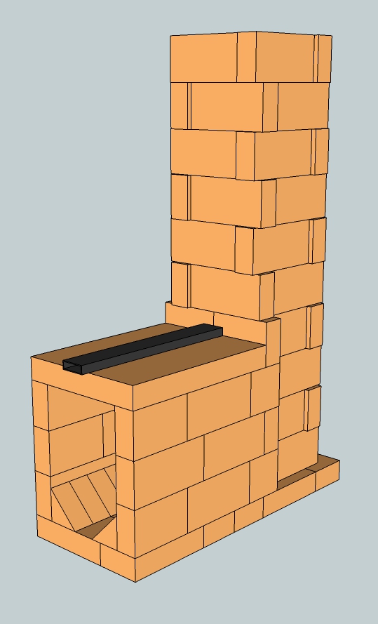
This is a complete core, system (riser diameter) size 150 mm (6") built of fire bricks. There are a couple of ways of closing the top of the firebox. The drawing shows a fire brick plate, there are traders in most countries who sell these. A top plate out of refractory castable is also a possibility, when a mold is simple to make and a vibrating table is already at hand. Another way to do it is laying bricks in a cantilever arrange, since they are too short to cover the distance in one span.
In order to try this construction outside in the open air normal red bricks can be used and a concrete sidewalk paver as top plate. Don't expect it to survive for long but it gives an indication what is actually happening inside. A sizeable mirror held at an angle of 45 degrees above the riser will allow spectators to view down and see what is happening in there. Be careful though, at full tilt this core is capable of spitting out a temperature of 700 ºC (1470 ºF) quite easily.
Dry stacking of the bricks won't work, too much air is drawn in through all the small holes and crevices. Complete combustion won't happen because of this. In order to seal it clay and sand could be used or even mud slurry between the bricks would be adequate. Also thin set for tile work from Home Depot or something like that would work. Another material suitable to try things out is air entrained concrete, sold under a plethora of names all over the world. This is light, insulative and cheap, easy to cut with a normal hand saw and sports limited heat resistancy.
All versions of the p-channel (the black steel tube which runs over the firebox and ends directly over the port) are best lit by means of a small kindling fire directly in front, but definitely not in, the port. When that fire is burning well the rest of the batch quantity can be loaded. Load the fuel only lengthwise, front to back with few spaces between pieces. Leave at least 50 mm (2") free between the fuel and the ceiling of the firebox. Take care there's no fuel, however small, sticking in the port itself. When it is, this will result in a badly smoking device, garanteed.
Casting a core
This can be done using refractory concrete, also refractory castable, consisting of aluminum cement and among others ground fire brick as aggregate. Molds need to be made, the castable need to be mixed with as little water as possible and a vibrating table is best to drive the air out. It can be done without that table but the end quality won't be as good.
The molds can be made out of sheet material such as coated plywood and screwed together. The internal shapes and cavities can be formed by using extruded polystyrene foam or any suitable material that can be shaped by you, MDF, builders bog, wood. Working this materials can be done with a good table saw machine. Details are easily done with coarse sandpaper, especially when using the foam. The pieces can be glued inside the mold and onto each other using double sided tape, the type which is made to glue carpeting to the floor. Most of the time releasing the cast piece out of the mold means the shaping material need to cut/chiseled out of the cast.
Below is an example of a mold which is made like that. The pictured mold wasn't ready yet, this is only to show what it looks like.
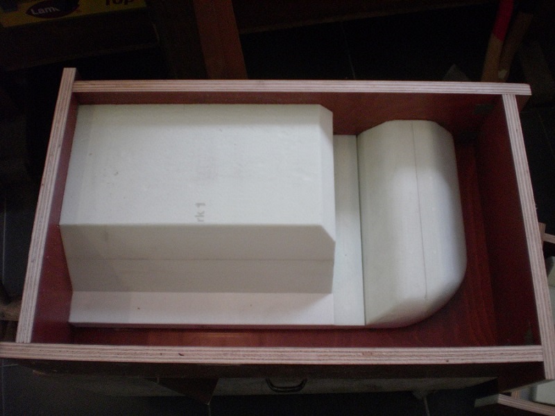
The disadvantage of a mold like this means it's a one-time affair, a one-off mold. Using this a couple of times or more isn't easily done unless the shape is very simple with large release angles. In order to do production runs it would be better to build a positive, called "mothermold" or "plug" out of woody material and cast a negative production mold out of polyurethane rubber. It's a professional opportunity and suited to commercial endeavours because the process and materials are quite expensive.
Applying a release agent in the mold prior to casting is necessary to aid release, because refractory concrete adheres very strongly to almost every surface, even steel. A lot of materials could serve as this agent, beeswax is good. Normally I use a mineral oil like two stroke oil or gearbox oil. Don't forget to wipe off excess oil with a rag, a very thin film is sufficient. Another mean to this end could be an aerosol canister of WD40 provided it's applied sparingly.
Use as litlle water as possible to mix through the concrete, much less water is needed for curing as compared to enough plasticity in order to become a workable material. A concrete mixer isn't actually suitable because for free fall to work lots more water is needed. Too little water in a concrete mixer leads to balling, inside every ball there will be material which isn't humidified. When the amount of concrete isn't too large the mixing can be done by hand, personally I have done this no other way than with a trowel and a mortar shell. The best solution is a paddle mixer but for one time use this is a very expensive solution.
In order to condense the concrete sufficiently by getting the air out, a range of techniques are available. Shaking, prodding, a mini poker vibrator, an impact drill with a bolt in, you name it. For a good quality refractory product done in a mold a vibrating table is actually indispensable. Such a table is an inelaborate utensil as opposed to a paddle mixer. Personally, many years ago I used waste crate timber to assemble one, a fat induction motor equipped with a bolt and an eccentric strip on the axle fixed under the top plate and two back springs of a moped cutted in half between frame and top plate.
But... it can be done much more simply. With a car tyre, a plate of plywood and an old drilling machine. Here is a video which shows how it is assembled.
In this video a real vibrating motor is used but a power drill fixed under the plate equipped with a simple eccentric would work as well. Even nicer: a small hand sander mounted under the top plate works perfectly. When possible, use a machine which is capable of variable speed. When an oil-like fluid is appearing on the surface of the refractory, stop vibrating. This is a sure sign of separation of the components which will result in a poor quality product when vibration is commenced.
As soon as everything is properly condensed place the mold on a flat and level surface. The product will become inevitably thicker on one side when the mold is off level. During curing the refractory will get hot, most of the water on the surface will evaporate whereby the cast side will become powdery. It would be best to cover the fresh cast with plastic sheeting to keep the water in. Most of the refractory castables can be released after 8 hours at room temperature. Ninety percent of maximum strength is achieved by that time, the rest will follow in about a week, sometimes two. In practise, the cast is kept in the mold overnight. Of course there's no objection to a longer stay in the mold.
To cast a core as a monolith without cracking when the core heats up is virtually impossible. This is caused by expansion of the material when heated. During a burn the temperature isn't equally distributed which is causing cracks. Where the cracks appear aren't the hottest spots but the coldest instead. The hotter parts start to expand and the cooler parts are staying behind and tearing apart. The solution is to be found in dividing the whole thing in such a way that the hotter and cooler parts are separated. The seams can be sealed with aluminum silicate paper and the parts held together by means of steel wire, a large hose clamp or a steel support frame.
It is very sensible to keep the wall thickness small and where applicable to stick fill pieces in the mold. The mass will be as low as possible this way, less mass to warm up will mean the thing is quicker up to working temperature.
The Bell, how it works and why
An important term that needs to be understood is "Bell". It has become part of the language of building these types of heaters and as such its usage and meaning must be understood. Contrary to what might be expected, it has nothing to do with a church bell or any other bell of that nature. It is nothing more than a large enclosed space, meaning 'four walls, a top and bottom'. It can be any shape that works best for the situation, it can be constructed of any material that suits the purpose best, including steel/metal, brick, refractory, stone, clay dug out of the backyard mixed with straw.
You can build for speed, you can build it for looks,
you can build it for cheapness and each purpose has a range of materials that suit that purpose.
When we put these two elements together, the combustion units described earlier coupled with a bell, we have made ourselves a bell heater. As you will see from some of the sketchup drawings we combine these two elements so that the very hot, very clean exhaust from the combustion unit enters the bell and 'allows the magic to happen'. The combustion unit can be external or internal to the bell.
So, having described what a bell is, it is simple to see how and why it works as well as it does. Hot exhaust gas from the combustion unit enters into the bell, and as we all know, hot air rises. As the bell is *very much larger* than the pipe feeding it with the hot exhaust, the hot exhaust does not rush through it as might be first assumed. As it enters the very much larger space of the bell it slows down immensely further allowing the principle of 'hot air rises' to take place. The hottest part of the gases rise to the top of the bell, and gives the heat it contains to the interior surface of the bell and in the process cooling, thus falling within the bell.
As hot exhaust is continually entering the bell, an exit must be provided (in other words, the 'normal chimney flue'). This exit is usually placed as low in the bell as practical. The converse of 'hot air rises' is naturally, 'cold air falls'. It is clear then that the gases which do leave the bell and out the chimney are the coldest gases. In this manner we can easily, and successfully, 'harvest the heat'. The advantages of this is not hard to imagine, all anyone needs to do is recall any normal wood burning space heater and remember how hot the flue gets. In fact, it might not be wrong to say in a conventional wood heater it is the hottest gases that escape, clearly not as good a solution as is being presented here.
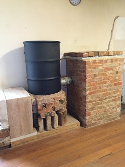
A picture tells a thousand words, what a bell is and how it works can be clearly seen below.
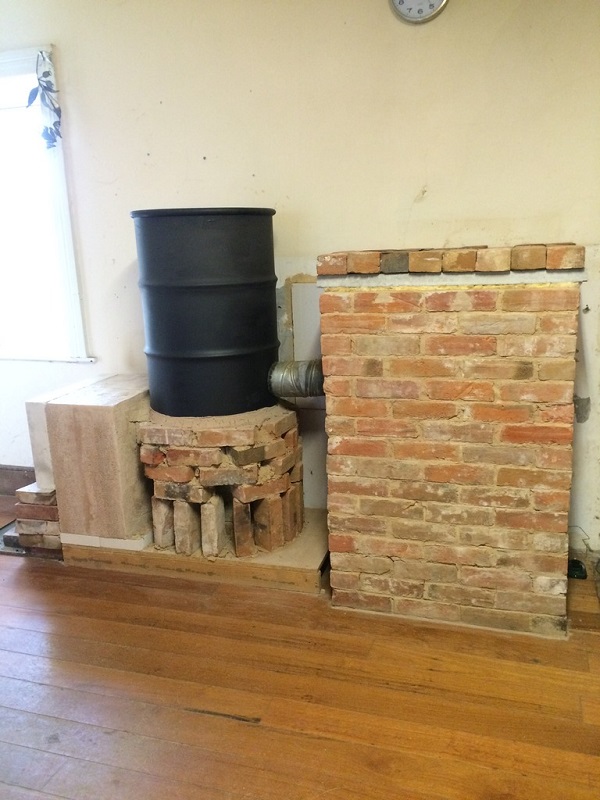
The entry of the hot exhaust from the metal oil drum (at left) can be seen to enter the single skin bell about halfway up. Looking closely at the bottom right, we can see where the temperature measuring probe enters the bell and into the exhaust flue. The inside of the bell is nothing but 'space'. It does allow the hot exhaust to enter, slow down greatly, rise to the top of the bell and give its heat to the bell, cool and then fall down to almost the floor before leaving the bell via the chimney flue. (The use of metal oil drums will be explained in an upcoming section, for now simply grasp the bell concept and how it works.)
The behaviour and the consequences of hot gases rising was first described in 1910 by V. E. Grum-Grzhimailo, professor of metallurgy at the university of Saint Petersburg.
Of course the simple description just above of how a bell harvests the heat does not reflect the true, more complex reality of what occurs. The simple description above was quite a static picture, the reality is that it is a constantly changing very dynamic system indeed. The internal walls of the bell do not 'only' trap the heat, the external walls of the bell radiate heat. At times the internal walls of the bell might get hot enough that they cannot absorb any more heat, and heat absorption will increase/be forced lower down the walls. As the heat carrying capacity of the bell is reached, the temperature of the escaping gases will rise (as they can no longer give heat to the walls). So, a constantly changing set of forces/actions occurring, yet even so the exhaust gas will almost never reach the same temperature as the incoming gas.
If the temperature of the exhaust gas is high enough, and the heat lost to the external world is wanted, then we can extend this idea of the bell by recognising that the exhaust of one bell can be considered as the heat input to another bell. This second bell works in exactly the same way as described above, the end result being that it's exhaust is lower than the temperature of the gases that entered it. This second bell concept is naturally more efficient (usually, ultimately it depends on what the flue temp is... if it is low enough with a single bell then the second is not needed as one bell has done the job). Adding a second bell could increase the efficiency of heat harvesting, but it also introduces greater complexity.
There are rules of thumb to come later that allow us to know the size of the bell that relates to the size of the combustion unit. At all times there must be a certain temperature in the exit flue (roughly 80 - 100 ºC / 175 - 210 ºF) in order for sufficient draw to occur. In other words, we cannot have cooler than ambient air as the flue temp.
An additional real advantage of the bell system is that it creates almost no, or negligible, friction or resistance to the flow of gases through it. That this is achieved with such a simple construction is an added bonus. By comparison, the German/Austrian way of building a mass/masonry heater uses a system of channels to give the heat to the mass. The surface area of these 'long' channels, coupled with the (relatively) small diameter of the channels themselves imposes much greater friction/resistance to the flow of gases. This then requires as a necessity that it be a very strong drafting system indeed in order to overcome the friction. In addition to all of that, we can see that ALL of the gases flow through all of the system together, the hottest together with the coldest as the separation of hot and cold (as in the bell) has not occurred.
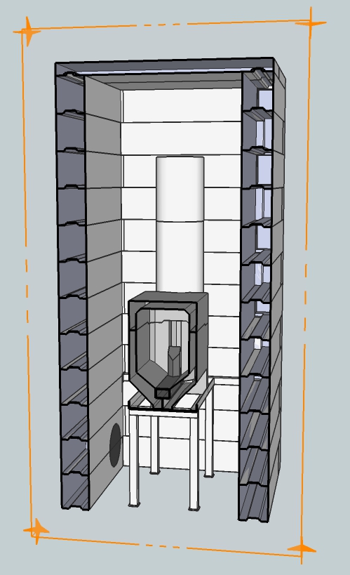
The 'simple' bell system, as pictured above, is very effective but has a singular disadvantage, all the mass is located within the single brick skin. This makes them 'large'. There are techniques available that can counteract that. Placing the combustion unit higher within the structure as opposed to floor level results in the storage of heat at a higher temperature because the gases need to sink lower than where the combustion unit is located. Additionally, internal structures (eg, columns) can be built inside the simple brick skin that can absorb, and then release later, heat. With such measures it is possible to reduce the size of bell needed using the simple 'single skin' method.
Almost all of the heaters to be described later are working bell systems in one way or another.
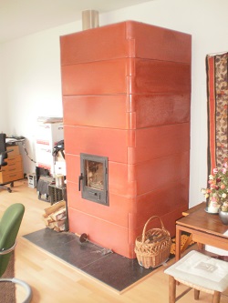
One last comment on the system pictured above. It is an example of what might be called a hybrid, half way between a bell and a metal drum system. It shows the combinations available for the demands required. In the above, the metal bell gives off radiant heat whilst it charges the bell as it exits the house. This brick bell has a four hour lag, by that is meant the exterior surface of the bell reaches its hottest temperature four hours after the fire has reached its hottest temperature. It had to be absorbed and travel from the internal surface of the bricks to the external surface before it can radiate to the room. Instant heat from the metal oil drum, stored heat that is released slowly over night (or indeed until the next burn) from the attached bell. As a matter of interest, the exit temperature of the flue gases (measured in the centre of the gas stream) stays within a range between 50 - 80 ºCelsius (120 -176º Fahrenheit). No doubt some cups of coffee are hotter than that.
Bell sizing
The size of a bell and it's method of calculation needs some clarification. Most people would suppose the heat extraction capacity of the bell is governed by volume, but this is not the case. Broadly speaking the governing factor is surface area, namely the walls and ceiling of the bell, so this is what is used in our sizing of the bell. The shape of the bell is almost insignificant, care only needs to be taken that the gases slow down enough and that undue friction is not created. In practice, the CSA of the bell should be at least 5 times the CSA of the entry flue. The gap between the top of the riser and the top of the bell should measure at least 30 cm (1'). In the vast majority of cases this will be sufficient, though more is better as the more the gases are slowed down the better the separation of hot and cold gases.
The correct sizing of the bell was hard won by experimentation, and like all open source projects contributions came from many different people. Klemen Urbanija from Radomlje, Slovenia found out after a lot of tinkering that a 15 cm (6") system with a single bell with an internal surface area of 6 m² (64.6 sq ft), excluding the floor, gave an exhaust temperature 60 ºCelsius (140 ºFahrenheit). He built his experiment outside the house and changed it several times until the results were satisfying, then he tore it down and moved it inside the house. A new round of problems emerged due to the chimney stack being made of bricks, which extracted heat from the exhaust thereby killing the draw. This needed more tinkering and rebuilding of the bell in order to raise the exhaust temperature and restore the draw. The final result was a figure of 5.3 m² (57 sq ft) of 'heat absorption area'. This is important to grasp, and once grasped it can be seen that the floor area of the bell will not be part of the 'heat absorption area' as the flue exits above it. Equally, if the firebox is built into the bell then the surface area of the firebox within the bell won't play a role in calculating this area as no heat is absorbed there.
The term we use for the total area available for heat absorption within the bell is ISA, short for Internal Surface Area. As noted, this does not include the floor area as that floor does not (directly) absorb heat. The difference between a steel bell which is shedding its heat immediately and one that is storing heat in a mass of stone or brick is marginal in terms of ISA. My workshop heater (see article Three barrel batch rocket) is built out of three oil barrels which together are very close to the same ISA as Klemen's masonry bell and bench. Both systems have a comparable exhaust temperature.
Scaling up of these numbers posed a long-standing problem which was finally solved in 2015. It turned out that the same critical dimension used to scale the size of fireboxes up or down, the cross sectional area of the heat riser, can also be used to scale the bell ISA up and down from the base result determined by Klemen. 2015 was the year that the bell with two cul-de-sac benches was built during the MHA meeting (see article Bell with dead-end benches). The maximum ISA of that 20 cm (8") system and a masonry bell without chimney bypass turned out to be 9.4 m² (101 sq ft). The ratio of Klemen's heat riser CSA to the MHA riser CSA was 1 : 1.77, and the same ratio of 1 : 1.77 appeared in both ISAs. We had found it!
As a consequence we can use the following 'table', and simply extrapolate or interpolate as required. As far as we know, this method works within reasonable limits in both directions.
Riser diameter / Internal Surface area
- 12.5 cm (5") ISA 3.7 m² (39.8 sq ft)
- 15.0 cm (6") ISA 5.3 m² (57 sq ft)
- 17.5 cm (7") ISA 7.2 m² (77.5 sq ft)
- 20.0 cm (8") ISA 9.4 m² (101 sq ft)
- 22.5 cm (9") ISA 11.4 m² (123 sq ft)
- 25.0 cm (10") ISA 14.7 m² (158 sq ft)
When the bell is fitted with a chimney bypass it could be larger than the figures mentioned here but it will make the construction more complicated, not to mention vulnerable to malfunction.
Benen Huntley from Adelaide, South Australia found a simple rule of thumb for to calculate the maximum ISA of the bell for any given system size. Calculate the cross section area of the riser in square meters and multiply that by 300. This will give you the recommended maximum size of the Internal Surface Area (ISA) of a single bell.
For example: a 150 mm system will give you 0.0176715 sq m. Multiplied by 300 will result in 5.3014376 sq m, which rounded off to 5.3 sq m is exactly the recommended maximum value for such a system. Of course taking into account a 150 mm round riser is as good as a square riser with sides of 150 mm, aerodynamically speaking. The round riser is smooth, no corners. The square is larger but has corners and a larger circumference which pose friction to the gases. So in case of a square riser the cross section area of a round riser should be used for this.
Another example: a 200 mm system will give you a cross section area of 0.031415927 m². Again multiplied by 300 comes down to 9.424778 m², rounded off to 9.4 m² is exactly according to the recommended values.